SOM-1740-001.pdf - 第9页
8 Tg0934-PM-SO 5. Pick-up Error Confirmation Plate Replacement Pro- cedure • Press the bottom of the pick-up error confirmation plate against the passing side of the height confirmation jig and fasten it with a plate set…

7 Tg0934-PM-SO0310-001
4. Operation Description
4. Operation Description
(1) Turn on the power to the machine.
Refer to "Volume 1, Section 3 Scope of Automatic Operation" for
details.
(2) If an error occurs when the vacuum nozzle picks up a component
from the tape feeder then the component will be caught between
the tape feeding surface of the tape feeder and the suppressor
(vertical component).
(3) After the feeder carriage is moved, the pick-up error confirmation
plate A or B, will touch the error component and detect the error.
(4) The feeder carriage will be stopped immediately and the cycle op-
eration of the turn-table is also stopped.
Refer to "6. Trouble Shooting" for how to restore.
Note
8 Tg0934-PM-SO
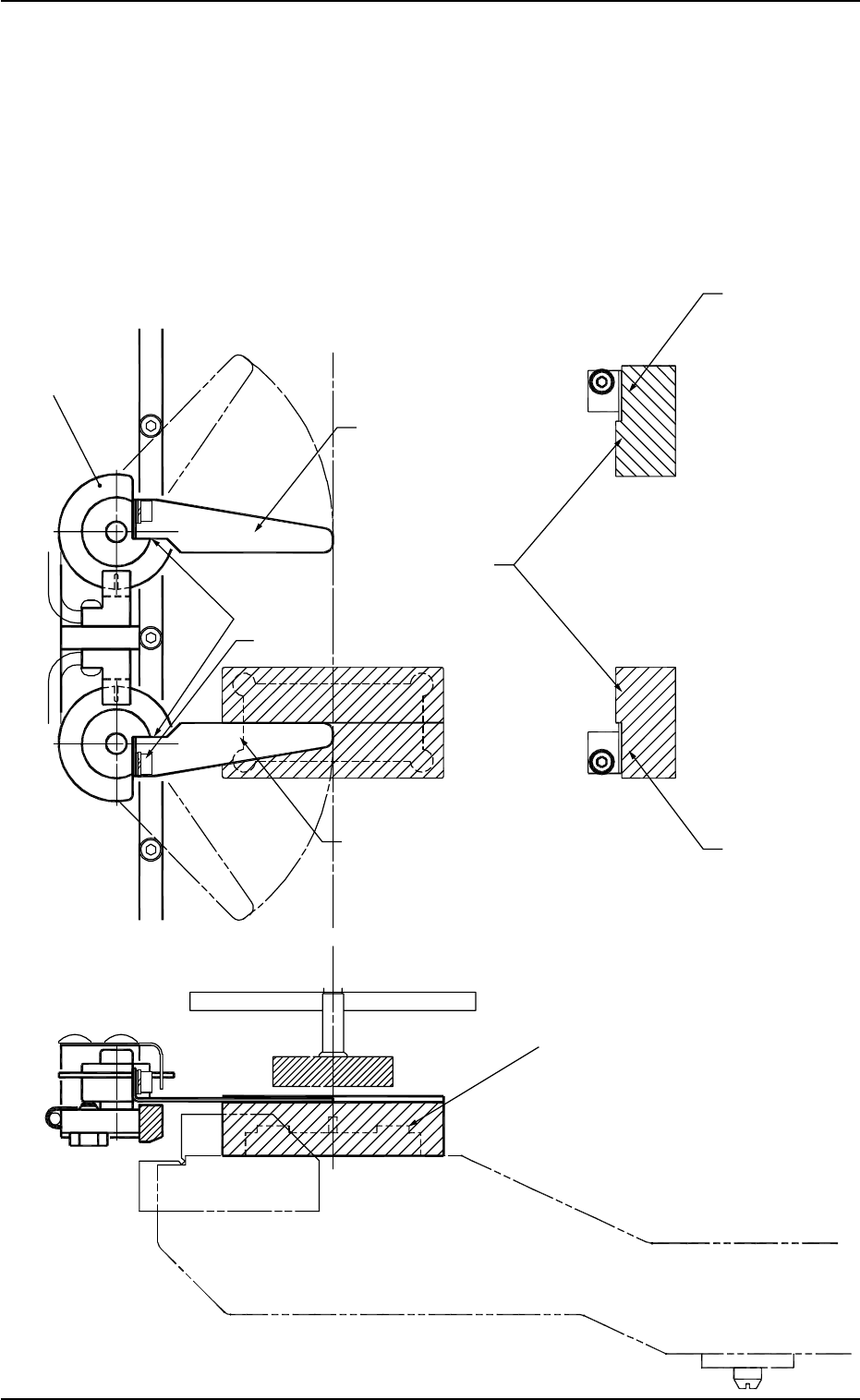
5. Pick-up Error Confirmation Plate Replacement Pro-
cedure
• Press the bottom of the pick-up error confirmation plate against the
passing side of the height confirmation jig and fasten it with a plate
set bolt.
Also, at the same time, press the pick-up error confirmation plate
against the shield disc on the stopper surface to fix.
0310-001
5. Pick-up Error Confirmation Plate Replacement Procedure
Fig. 3
Passing Side
Shield Disc
Pick-up Error Confirmation Plate A
Stopping Side
Stopper Surface
Plate Set Bolt
Pick-up Error Confirmation Plate B
Passing Side
Height Confirmation Jig
Master Jig
9 Tg0934-PM-SO0310-001
6. Trouble Shooting
6. Trouble Shooting
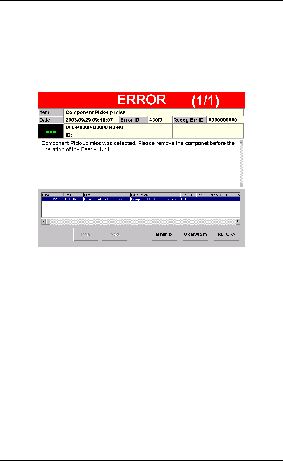
6.1 Error Display
When the large component pick-up error detection sensor touches the
error component and an error is detected then the following window
appears.
Fig. 4