00193732-02.pdf - 第55页
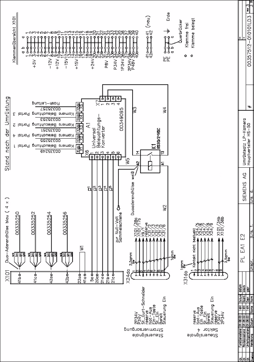
SIPLACE HS-50/HS-60 2 Retrofit Instructions for PCB Camera Mult icolor, HS-50 / HS-60 11/2004 Edition 2.6 Changeover at Main Distribution Frame 55 2 Hauptverteiler HS-50 / H S-60, Verdrahtung nach der Umr üstung 2
2 Retrofit Instructions for PCB Camera Multicolor, HS-50 / HS-60 SIPLACE HS-50/HS-60
2.6 Changeover at Main Distribution Frame 11/2004 Edition
54
: Clip the universal illumination converter board, relay K1 and the two terminals 41 and 42 onto
the top-hat rail.
: Connect the terminals of plug connector X6dp (previously identified) at plug connector X6.
: Connect plug-in connectors X1 to X5 for the camera illumination and flash wire on the illumi-
nation converter.
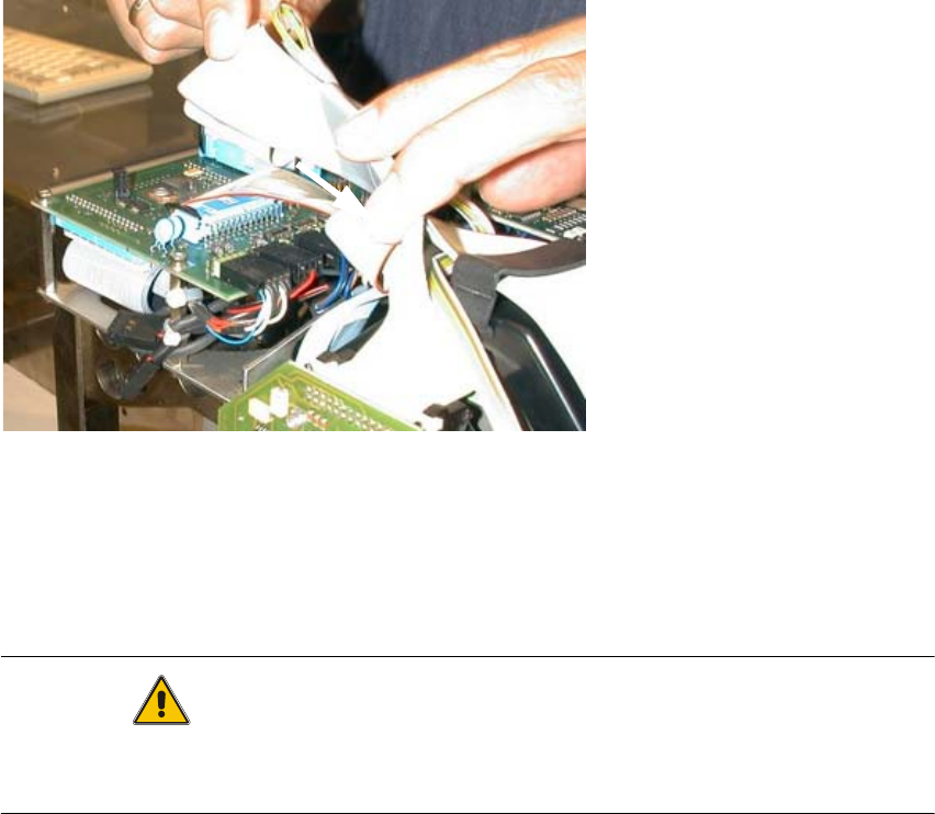
: Replace each of the four AMP connectors for the power supplies to the stepping motors with
a blue ferrule (see picture).
: Now connect wire 00335250-xx (stepping motor) at X101 / 41b.
: Now connect wire 00335252-xx (stepping motor) at X101 / 41c.
: Now connect wire 00335254-xx (stepping motor) at X101 / 42a.
: Now connect wire 00335256-xx (stepping motor) at X101 / 42b.
: Insert the jumper (gray) in terminals 41/42.
: Connect cable W1 at X101 / 22a and X101 / 41a.
: Press the pin contact 9 of connector X24do (yellow) and socket contact 6 of connector X31do
(black) out of the housing.
Use the AMP extraction tool to do this.
This connection is not necessary any more.
: Press the socket contact of wire W2 into connector X31/6.
: Press the pin contact of wire W2 into connector X24/9.
: Connect the ferrule of wire W2 to terminal A1 of the relay.
: Connect terminal X7/2 to terminal 14 on the relay (W3).
: Connect terminal X7/1 to terminal 13 on the relay (W4).
: Connect terminal X6/6 to wire W5 with a twin ferrule and connect wire W5 at terminal A2 on
the relay.
2
2
2
2
2
2
2
2
SIPLACE HS-50/HS-60 2 Retrofit Instructions for PCB Camera Multicolor, HS-50 / HS-60
11/2004 Edition 2.6 Changeover at Main Distribution Frame
55
2
Hauptverteiler HS-50 / HS-60, Verdrahtung nach der Umrüstung 2
2 Retrofit Instructions for PCB Camera Multicolor, HS-50 / HS-60 SIPLACE HS-50/HS-60
2.7 Installing PCB Camera Board and PCB Camera Multicolor 11/2004 Edition
56
2.7 Installing PCB Camera Board and PCB Camera
Multicolor
Possibly at HS-50 the modular head PCB is not mounted yet. 2
2
Fig. 2.7.1 "Conversion PCB small axis" still installed (= old PCB version)
: If the conversion PCB "small axis" is still installed on the placement head, retrofit the modular
head PCB unit now. Retrofit kit and instructions see chapter 2.2.
At HS-60 the modular head PCB unit is installed. 2
CAUTION
Comply the ESD regulations during the following handling of the PCBs.
Make certain that no screws or other parts drop into the machine or the placement head !! 2
2
1