00193732-02.pdf - 第72页
2 Retrofit Instructions for PCB Camera Multicolor, HS-50 / HS-60 SIPLACE HS- 50/HS-60 2.92 Safety Check: Shutdown of Illumination 11/2004 Edition 72 : Exi t the me nu "(Ga ntry 1) PCB cam e ra" . : In the menu …
SIPLACE HS-50/HS-60 2 Retrofit Instructions for PCB Camera Multicolor, HS-50 / HS-60
11/2004 Edition 2.9 SITEST: Configuration and Illumination Check of all PCB Cameras Multicolor
71
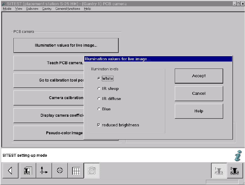
: The screen "Illumination values for live image" is displayed (using S-25 HM as an example):
Fig. 2.91.3 Screen: "Illumination Values for Live Image"
: Test at least the illumination levels "White" and "Blue" because their light is visible.
: Click on the "Radio button" to select the illumination level "White".
: Deactivate the button "Reduced brightness" and click on the button "Accept".
The complete illumination level is therefore activated at the outset.
: Switch to the menu "Teach PCB camera" -> Click on the button "PCB camera":
Make a visual check (with safety hoods closed):
The camera’s white light must flash.
: Once again, press the button "Illumination values for live image".
: Now activate the option "Reduce illumination".
This reduces the illumination level by one-half.
: Click on the button "Accept" again.
: Make a visual check (with the safety hoods closed):
The camera’s white light must flash repeatedly but not as brightly as before.
: Execute the above-described check for illumination level "blue" as well.

2 Retrofit Instructions for PCB Camera Multicolor, HS-50 / HS-60 SIPLACE HS-50/HS-60
2.92 Safety Check: Shutdown of Illumination 11/2004 Edition
72
: Exit the menu "(Gantry 1) PCB camera".
: In the menu "PCB functions" select the button "PCB camera" of gantry 2 or 3 or 4
Perform the above-described operation for these PCB cameras Multicolor.
NOTE:
If you would like to check the IR illumination levels too, perform the above-described operation in
a like manner for these levels also and. Place a white sheet of paper under the camera. As a
check, switch over to the vision screen in each case. 2
: Afterward, test to make certain that the camera illumination goes OFF in response to safety
shutoff:
2.92 Safety Check: Shutdown of Illumination
: Activate again - as described above - visible camera illumination at each gantry and, while the
light is starting to flash ON, open a safety hood or a cover (PCB input / PCB output):
: Check: The light must turn OFF when this occurs. This results from the interruption of the cur-
rent from the voltage regulator module (50 V) by the retrofitted safety relay.
: If an error occurs, check and correct the wiring on the basis of the circuit diagrams.
: Repeat this procedure with the key-operated switch in the normal position and in the service
position. The vision screen must remain dark!
: Continue with the illumination setting.
SIPLACE HS-50/HS-60 2 Retrofit Instructions for PCB Camera Multicolor, HS-50 / HS-60
11/2004 Edition 2.93 Illumination Setting
73
2.93 Illumination Setting
: Adjust the illumination setting at the station to the current substrate to be placed, proceeding
as described below.
2.93.1 Possible Illumination Settings and Selection Criteria
The following types of illumination are possible with the PCB camera Multicolor by using the per-
tinent setting (see Abschn. 2.12.3): 2
– Standard light:
Using this mixture of white and IR light it is possible to recognize a broad range of fiducials. By
selecting special types of illumination, the contrast of the image can be improved and, as a
consequence, the range of recognizable fiducials increased.
– White light:
This is used for standard PCBs (tinned fiducials).
– Blue oblique illumination:
By using this light, an obvious improvement in contrast can usually be attained where bright
fiducials on a light base material are involved, e.g., on ceramic or CEM. In a few instances,
fiducials covered by solder resist can also be recognized better on a light background.
–IR light:
It is usually practical to use this type of illumination for fiducials that are covered by solder resist
or for fiducials on flex material. It may also be possible to improve recognition where silver-pla-
tinum fiducials on ceramic are involved. Ascertain this in advance by conducting a trial cen-
tering and/or a trial placement.