00198158-01_AI_Speed_Config_RV12_NC_EN.pdf - 第13页
Speed (Single-Sided) DLM-RV12 - Option 1 Assembly Instructions E by SIPLACE 13 2 2 S p e e d ( S in g le - S id e d ) D L M - R V 1 2 - O p t io n 1 Speed (Single-Sided) DLM-RV12 - Option 1 A standard single sided machin…
Introduction
Staff Qualifications and Training 1.3.4 Release History
12 Assembly Instructions E by SIPLACE
1.4
1.4 Staff Qualifications and Training
Staff Qualifications and Training
Qualified or adequately trained personnel means that these people are familiar with the setting up, op
-
eration and maintenance of automatic placement systems and add-on devices and are suitably qualified,
e.g.:
▪ Have been trained, instructed or authorized to switch on and off, isolate, earth and identify electrical
circuits and system components in accordance with normal safety standards.
▪ Have been trained or instructed in the upkeep and use of appropriate safety equipment in accord
-
ance with normal safety standards.
▪ Have received first aid training.
Speed (Single-Sided) DLM-RV12 - Option 1
Assembly Instructions E by SIPLACE 13
2
2 Speed (Single-Sided) DLM-RV12 - Option 1
Speed (Single-Sided) DLM-RV12 - Option 1
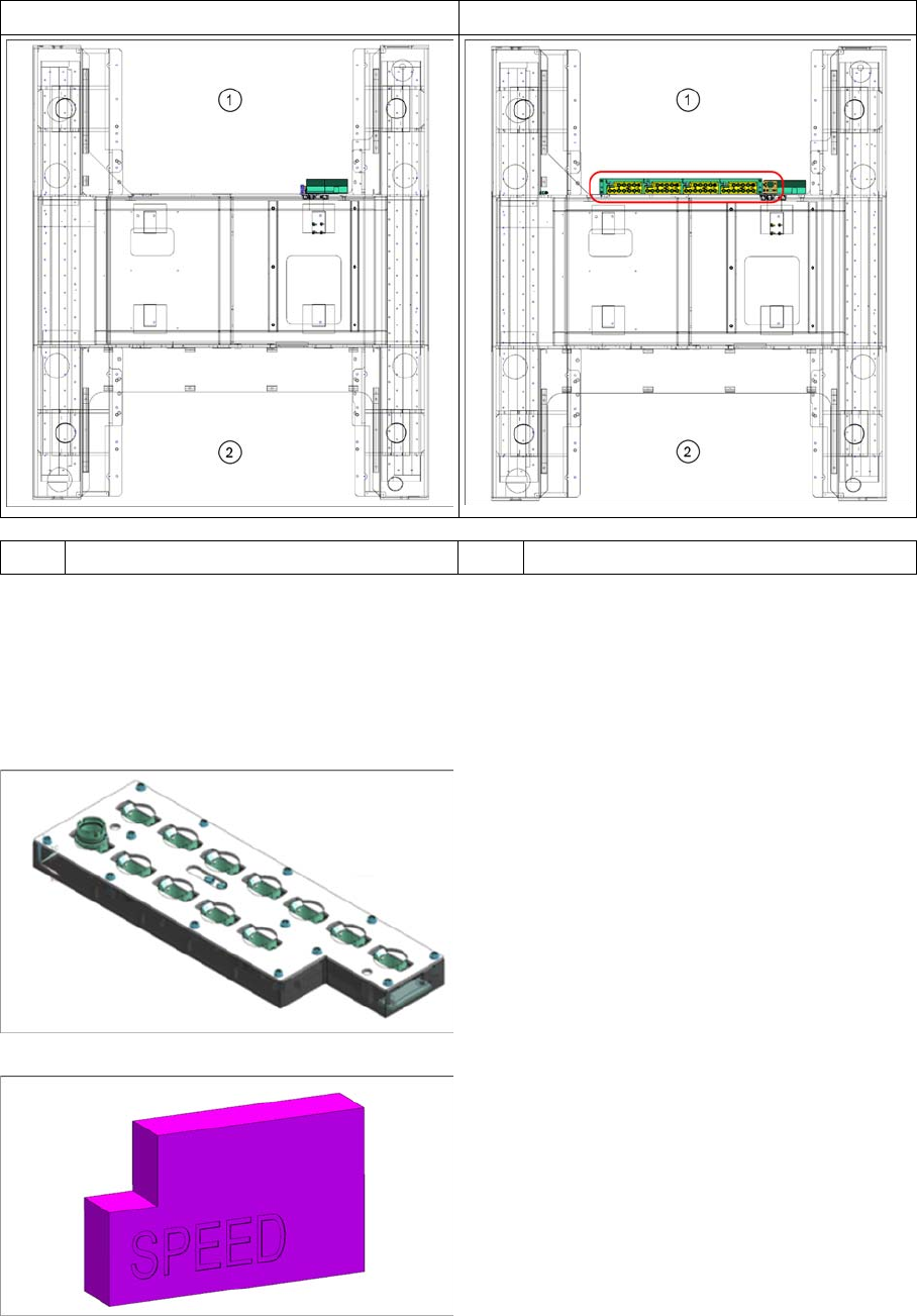
A standard single sided machine includes an "NC Speed kit reject bin small" [03113189-xx].
"NC SPEED RV12 LOC 1 cpl." [03113197
-
xx] is located in the highlighted area.
▪ It consists of a "single row nozzle changer" [03106322-xx] base plate with four "active nozzle mag
-
azines" [03081446
-
xx] as shown above.
▪ For an upgrade in the field, the height measurement block SPEED [03119428 xx] must also be or
-
dered.
Nozzle maga zine type 30xx fo r RV12 [03081446-xx]
Height measurement block SPEED [03119428-xx]
Standard Speed (SS) RV12 Speed (SS) RV12 Option 1
1 Location 1 2 Location 2
Active nozzle magazine type (quick reference)
▪ Nozzle magazine type 30xx for RV12
[03081446
-
xx]
Height measurement block SPEED [03119428
-
xx]
Speed (Single-Sided) DLM-RV12 - Option 1
Installation Procedures
14 Assembly Instructions E by SIPLACE
2.1
2.1 Installation Procedures
Installation Procedures
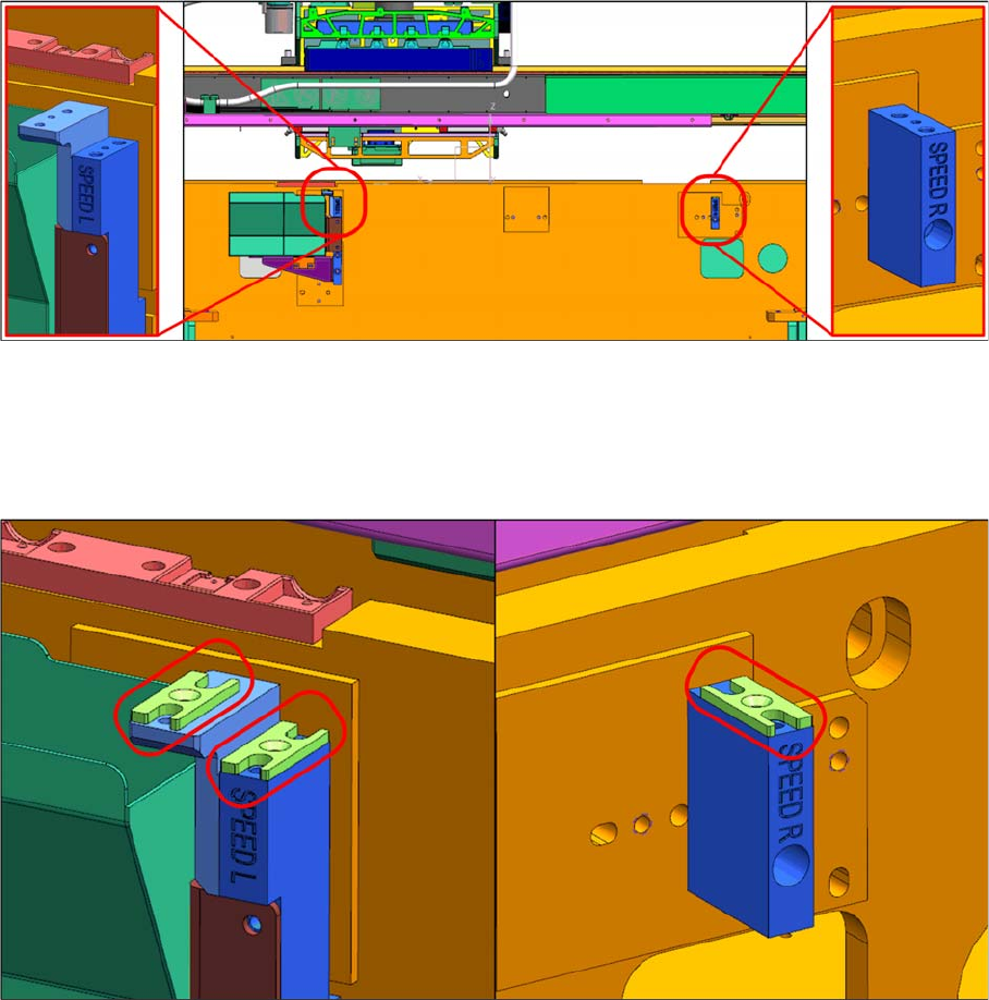
► Mount "Nozzle station support" [03105456-xx] onto "NC mounting bracket FLEX 1 Left" [03109945-
xx] using two M4x10 countersunk screws.
► Mount "NC mounting bracket SPEED right" [03108035-xx] onto the machine base frame using an
M5x30 cap screw.
► Mount one shim cover [03108393 xx] each on "NC mounting bracket Speed left" [03108126 xx] and
"NC mounting bracket Speed" right [03108035 xx].