00198158-01_AI_Speed_Config_RV12_NC_EN.pdf - 第20页
Speed (Single-Sided) DLM-RV12 - Option 2 Installation Procedures 20 Assembly Instructions E by SIPLACE ► Mount the "Reject bin holder" [03110727 - xx] (1) using two "M4x8 butto n head scr ews" [030452…
Speed (Single-Sided) DLM-RV12 - Option 2
Installation Procedures
Assembly Instructions E by SIPLACE 19
3
3 Speed (Single-Sided) DLM-RV12 - Option 2
Speed (Single-Sided) DLM-RV12 - Option 2
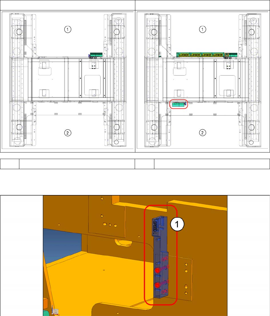
A "SPEED (Single-Sided) option 1" configuration can be enhanced with "SPEED Option 2", which con
-
sists of an additional "NC Speed kit reject bin small" [03113189
-
xx] and a "Module sensor reject box
LOC2" [03102729
-
xx] located at location 2.
3.1
3.1 Installation Procedures
Installation Procedures
► Mount the "NC mounting bracket Speed left" [03108126
-
xx] (1) onto the machine frame using two
5x12 dowel pins and two M5x30 cap screws.
STANDARD SPEED (SS) RV12 SPEED (SS) RV12 OPTION 2
1 Location 1 2 Location 2
Speed (Single-Sided) DLM-RV12 - Option 2
Installation Procedures
20 Assembly Instructions E by SIPLACE
► Mount the "Reject bin holder" [03110727
-
xx] (1) using two "M4x8 button head screws"
[03045201
-
xx].
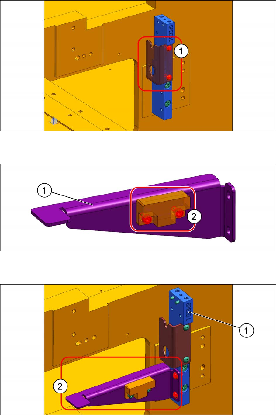
► Mount the "Module sensor reject box Loc2" [03102729
-
xx] (2) onto the "Sensor mount"
[03105704
-
xx] (1) using two "M3x6 cap screws" [03042541
-
xx].
► Mount the "sensor and sensor mount subassembly" (2) onto the "NC mount bracket Speed left"
[03108126
-
xx] (1), using two "M4x8 button head screws" [03045201
-
xx].
Speed (Single-Sided) DLM-RV12 - Option 2
Installation Procedures
Assembly Instructions E by SIPLACE 21
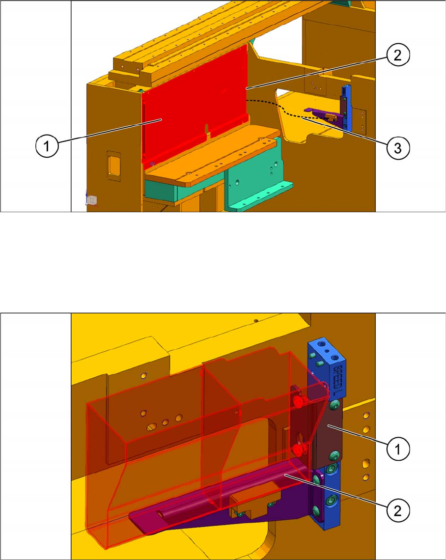
► Remove the "Top panel cover 3" [03106628
-
xx] (1) in location 2.
► Connect the cable of the "Module, sensor, reject box Loc2" [03102729
-
xx] (3) to the "Cable ext reject
box sensor Loc2" [03102692
-
xx].
► Run the cable through the opening (2) of the top panel cover.
► Refit the cover to the machine frame.
► Place the "Reject bin small" [03109739
-
xx] (2) into the "Reject bin holder" [03110727
-
xx] (1) key
holes.