TR7500_Hardware_en.pdf - 第3页
2 4 . 2 .7 S e n s o r .. . .. . .. . .. . .. . .. . .. . .. . .. . . . .. . .. . .. . .. . .. . .. . .. . .. . .. . .. . .. . .. . .. . .. . .. . .. . . . .. . .. . .. . .. . .. . .. . .. . .. . .. . .. . .. . .. . .. .…

1
Content
1 THE HUMAN-MACHINE INTERFACE & PLC......................................................................................................3
1.1 ARCHITECTURE AND FUNCTION.............................................................................................................................3
1.2 HUMAN MACHINE INTERFACE OPERATING INSTRUCTIONS ......................................................................................3
1.3 HUMAN MACHINE INTERFACE ALERT MESSAGES AND CAUSES.............................................................................19
1.4 HUMAN MACHINE INTERFACE PROGRAM REPLACEMENT......................................................................................22
1.5 PLC PROGRAM REPLACEMENT............................................................................................................................25
1.6 PLC HARDWARE OVERVIEW ...............................................................................................................................28
1.6.1 CPU(FP2-C1) Unit........................................................................................................................................28
1.6.2 Four Axis Controller (FP2-PP4) Unit............................................................................................................29
1.6.3 I/O (FP2-XY64D2T & FP2-Y16P) Unit..........................................................................................................30
2 CONVEYOR BELT..................................................................................................................................................31
2.1 ARCHITECTURE AND FUNCTION...........................................................................................................................31
2.2 SENSOR ADJUSTMENT AND REPLACEMENT...........................................................................................................31
3 SUPPORT PIN..........................................................................................................................................................32
3.1 ARCHITECTURE AND FUNCTION...........................................................................................................................32
3.2 INSTALLATION ....................................................................................................................................................32
3.3 CONFIGURATION PROCEDURE..............................................................................................................................32
3.4 WIRING DIAGRAM ..............................................................................................................................................34
4 MODULE BOARD....................................................................................................................................................35
4.1 ARCHITECTURE AND FUNCTION...........................................................................................................................35
4.1.1 TR7500 Front Module Board Layout..............................................................................................................35
4.1.2 TR7500 Back Module Board Layout...............................................................................................................36
4.1.3 TR7500 Side Module Board Layout................................................................................................................37
4.1.4 Module Board (7100-006-6)...........................................................................................................................38
4.1.5 TR7500 Distributor Box.................................................................................................................................39
4.1.6 TR7500 Lighting Control Box........................................................................................................................40
4.1.7 TR7500 Power Board Layout.........................................................................................................................41
4.1.8 TR7500 Chassis Casing.................................................................................................................................42
4.2 SYSTEM WIRING DIAGRAM .................................................................................................................................43
4.2.1 System...........................................................................................................................................................43
4.2.2 EMS..............................................................................................................................................................45
4.2.3 PC PORT......................................................................................................................................................45
4.2.4 PLC I/O.........................................................................................................................................................46
4.2.5 PLC & DRCH I/O & EMS.............................................................................................................................47
4.2.6 Relay Model..................................................................................................................................................48
2
4.2.7 Sensor...........................................................................................................................................................48
4.2.8 Conveyor & Motor & Signal Tower................................................................................................................49
5 AUTOMATIC CONVEYOR WIDTH ADJUSTMENT...........................................................................................50
5.1 ARCHITECTURE AND FUNCTION...........................................................................................................................50
5.2 WIRING DIAGRAM .............................................................................................................錯誤! 尚未定義書籤。
5.3 AUTOMATIC CONVEYOR WIDTH SETTINGS...........................................................................................................50
6 SERVICE..................................................................................................................................................................51
6.1 PC/PLC CONNECTING.........................................................................................................................................51
6.1.1 Opening the PC I/O Testing Display...............................................................................................................51
6.1.2 Open the PLC I/O Testing Display..................................................................................................................52
6.1.3 Testing Method..............................................................................................................................................53
6.1.4 Hardware Wiring:..........................................................................................................................................53
6.1.5 System Configuration:...................................................................................................................................54
6.2 AUTOMATIC CONVEYOR WIDTH..........................................................................................................................55
6.2.1 Stepping Motor Driver Problem.....................................................................................................................56
6.2.2 Wiring Problem: Refer to the Wiring Diagram................................................................................................56
6.3 CONVEYOR BELT ................................................................................................................................................57
6.3.1 Sensor Problem
-
Adjustment:.......................................................................................................................58
6.3.2 Check Stepping Motor Driver Problem...........................................................................................................58
6.4 HOLDER MOTOR.................................................................................................................................................60
6.4.1 Check Stepping Motor Driver Problem...........................................................................................................61
6.4.2 Replacement:.................................................................................................................................................61
6.5 INLINE.............................................................................................................................................................62
6.5.1 Does Not Load...............................................................................................................................................62
6.5.2 Does Not Unload Unloader............................................................................................................................62
6.5.3 Signal Meaning.............................................................................................................................................62
6.6 X-Y TABLE ALARM.........................................................................................................................................65
6.6.1 Check Driver Error Codes.............................................................................................................................65
6.6.2 EzLINK.........................................................................................................................................................72
6.7 PLC ERROR......................................................................................................................................................83
3
1 The Human-Machine Interface & PLC
1.1 Architecture and Function
The Human-Machine Interface (HCI) is mainly used to set the required testing mode
(settings such as Stand-Alone or Inline, whether the Loader or Unloader are present etc.). The
PLC is mainly used to control the PCB I/O Board, Holder as well as exchange sampling or
Pass/Fail signals (through the RS-232 cable); usually when the machine is set to In-Line mode
there will be a greater chance of I/O board issues or loader/unloader error. The possible errors
and solutions are introduced below:
1. If the PCB to be tested is relatively long, when the testing is completed and the PCB is
unloaded and the next PCB loaded, the PCBs may cover Sensor1 (Loader Sensor) and
Sensor2 (Brake Sensor) at the same time. The current program logic of the PLC requires that
Sensor1 and Sensor2 must not both be triggered at the same time, or the Buzzer will activate
and the board will automatically be unloaded. In such a situation the relative positions of
Sensor1 and Sensor2 should be adjusted to avoid being simultaneously triggered and
leading to abnormal operation. The exception is when equipment is set for simultaneous IN
and Out.
2. Loader/Unloader Connection: Please install wiring according to SMEMA specifications.
Additionally on Port 2 pin5/6 there’s a short signal provided during Test Pass.
#The above connections are all single point relays so there are no positive or negative
polarity differences.
1.2 Human Machine Interface Operating Instructions
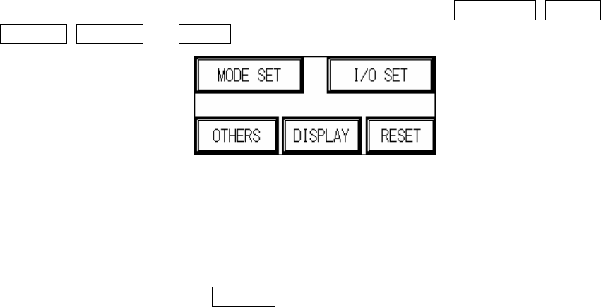
1. Starting display Figure 1.1 : wait approximately 5 seconds after power on, and the display will
jump to the starting page Figure 1.1. Five options will be shown: MODE SET, I/O SET,
OTHERS, DISPLAY and RESET.
Figure 1.1 Starting Display
1.1 MODE SET (Figure 1.2): Can choose between Inline mode, Stand-Alone mode or Test
Mode. (Will be automatically stored during shut down, and automatically loaded at the next
power on.)
1.1.1 INLINE mode: Connect to external equipment for inline testing.
1.1.2 INLINE mode (hiding BYPASS button on standby screen): Press the hidden button