TR7500_Hardware_en.pdf - 第6页
5 T E S T C O UN T , N EX T , UN L O A D E R a n d BA C K . F i g u r e 1 . 5 O T H E R S 1 . 3 . 1 C O N V . W I D T H (F i gu r e 1 . 6 ) : P r e s s C O N V . W I D T H i n F i g u r e 1 . 5 a n d A U T O o r M A NU A…
4
at the lower right corner at least 2 seconds then press INLINE button. The INLINE
button turns to black, then select INLINE button to hide the BYPASS button on
standby screen (Figure 1.32).
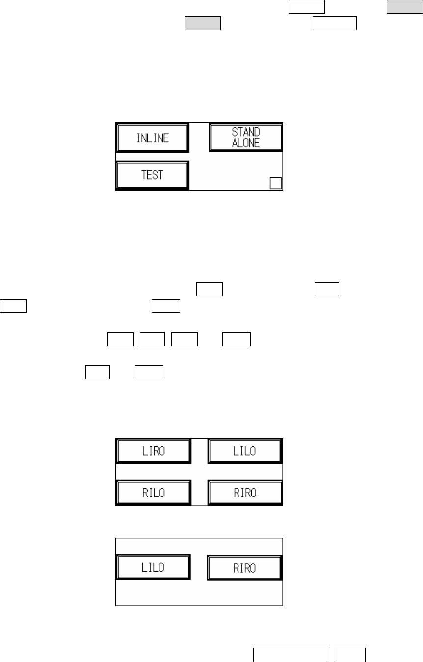
1.1.3 STAND-ALONE mode: Do not connect to external equipment for testing, requires
manual loading and unloading.
1.1.4 TEST mode: Single board test, does not connect to external equipment for inline
testing, may choose number of test cycles.
Figure 1.2 MODE SET
1.2 I/O SET: Choosing different modes in MODE SET will result in different I/O settings. The
settings are as follows. (Will be automatically stored during shut down, and automatically
loaded at the next power on.)
1.2.1 INLINE mode I/O SET: If Inline mode is selected, the display will show Figure 1.3, with
four options available: Left-In-Right-Out (LIRO), Left-In-Left-Out (LILO), Right-In-Left-Out
(RILO) and Right-In-Right-Out (RIRO).
1.2.2 STAND-ALONE mode I/O SET: If Stand-Alone mode is selected, the display will show with
four options available: LIRO, LILO, RILO and RIRO.
1.2.3 TEST mode I/O SET: If Test mode is selected, the display will show Figure 1.4, with two
options available: LILO and RIRO.
1.2.4 Attention: The factory default is Left In mode, if the direction is changed to Right In mode,
then Sensor2 (Brake Sensor) and Sensor 3 (Position Sensor) positions and metal
connectors need to be switched.
Figure 1.3 INLINE and STAND-ALONE mode settings
Figure 1.4 TEST mode I/O settings
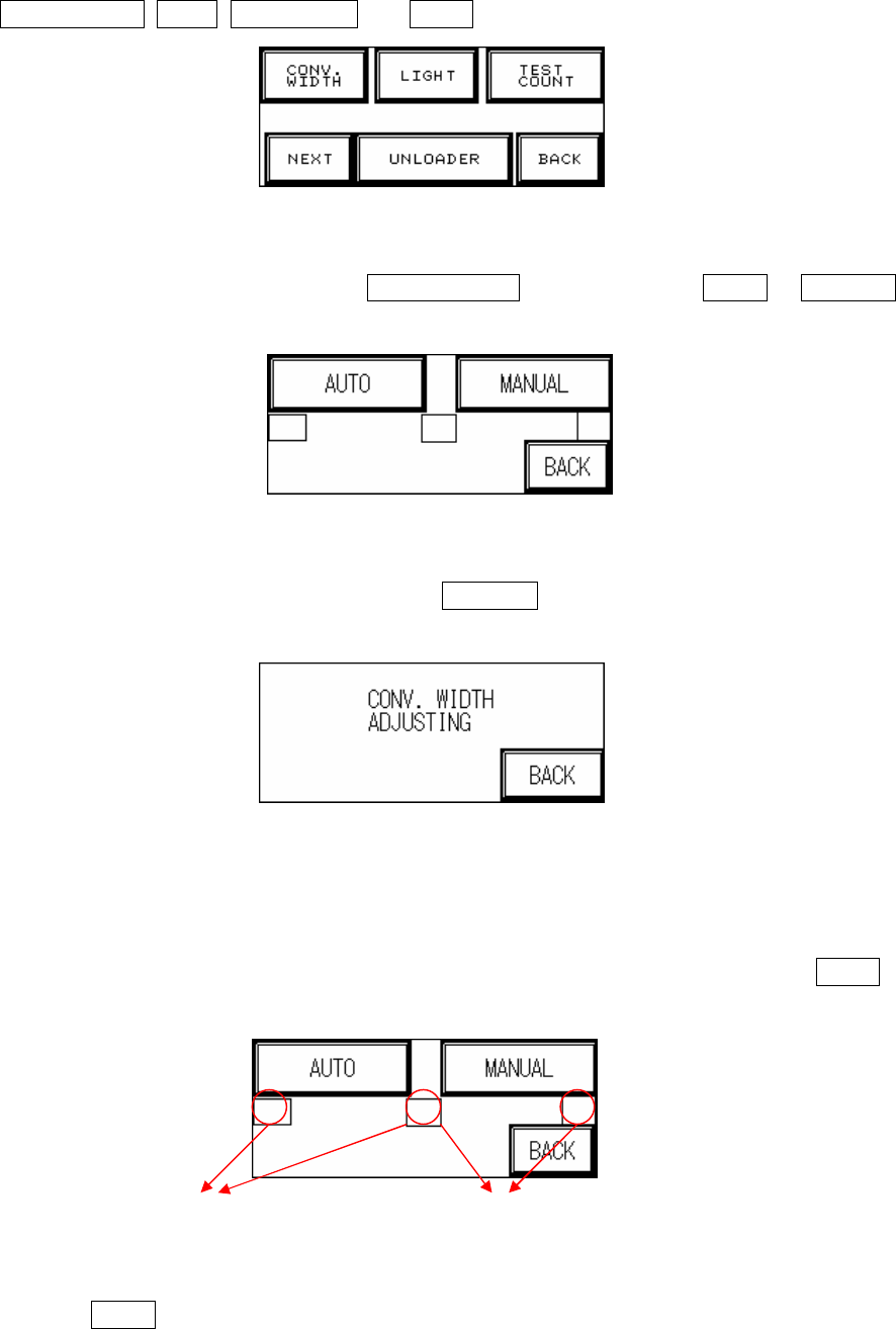
1.3 Other Settings (Figure 1.5): Six options are available: CONV. WIDTH, LIGHT,
5
TEST COUNT, NEXT, UNLOADER and BACK.
Figure 1.5 OTHERS
1.3.1 CONV. WIDTH (Figure 1.6): Press CONV. WIDTH in Figure 1.5 and AUTO or MANUAL
adjustment can be selected in Figure 1.6.
Figure 1.6 CONV. WIDTH setting
1.3.1.1. MANUAL Adjustment (Figure 1.7): Press MANUAL in Figure 1.7 to use the wheel to set
the conveyor width.
Figure 1.7 Manual Conveyor Width Adjustment
1.3.1.2. AUTO Adjustment: To prevent PLC error due to no automatic conveyor width device
being installed when the PLC is set to AUTO CONV. WIDTH, two hidden buttons are
provided in Figure 1.7 to Enable/Disable the function. Only when Enabled can AUTO
adjustment be selected.
1.3.1.3. Press AUTO adjustment in Figure 1.7 and the conveyor width will return to the origin
(machine origin) first. If this is the first setting operation from the factory, once the
AUTO CONV. WIDTH
Hidden Button: Press
Both Together to Enable
AUTO CONV. WIDTH
Hidden Button: Press Both
Together to Disable
6
initialization process has been completed, the “Electrical Origin” must be set, with the
origin point blinking in Figure 1.8. The machine type’s maximum testable board width can
be adjusted here, which for the TR-7006L is 460mm. Once the setting is entered the PLC
will automatically memorize that value. Press BACK then perform the RESET operation,
and the next time this display is accessed then the origin point text will not blink. The test
board width can now be set according to the method described above. The settings for
conveyor width can also be set or read through the PC. If the electrical origin needs to be
set again, at the Figure 1.8 display press the hidden buttons located behind S. and D.
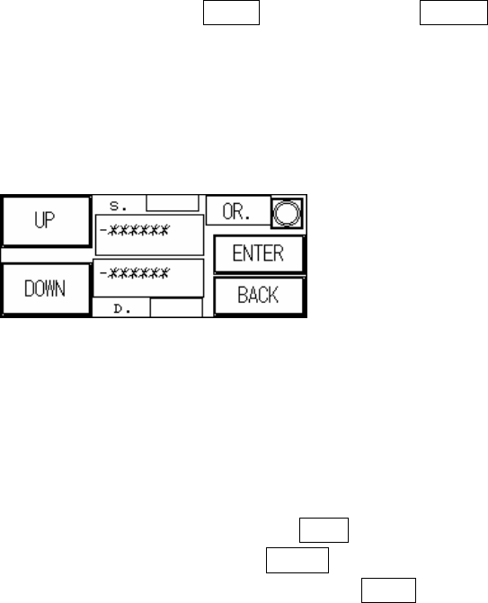
Figure 1.8 AUTO Conveyor Width Adjustment
1.3.1.4. Attention:
u All setting values have been idiot-proofed to prevent entry of negative
numbers.
u Figure 1.8 The indicator light at in the top right corner is the machine origin
Sensor. When light goes on after pressing wider button it means maximum
width has been reached. Below S. the -******* is the current conveyor
width position (unit: 0.008mm/pps); Above D. the -****** is the set
conveyor width position (unit 0.008mm/pps).
u When the conveyor width reset is in action, if there is a board to be tested
located over SENSOR1.2.3.4 then the alarm will go off and show the
Figure 1.9 display. Please remove the board before executing the Reset
operation.
u If the conveyor width operation times out before reaching the set position,
an alarm will ring and show the Figure 1.10 display. Please check the
conveyor width parts to see if they are correctly installed or malfunctioning.
u If an automatic conveyor width device is not installed and function is
accidentally triggered, this will cause a PLC Error that can not be Reset.
The PLC’s error indicator will show a red light. If this happens then the
machine power must be restarted. The PLC option must then be switched
to RUN then back to PROG, with CONV. WIDTH’s AUTO disabled and
changed to MANUAL.