TR7500_Hardware_en.pdf - 第8页
7 F i g u r e 1 . 9 P l e a s e R e mo v e B oa r d F i g u r e 1 . 1 0 A b n o r m a l O p e r a t i on f o r C O N V . W I D T H Mo t o r 1 . 3 . 2 I n d i c a t o r L i g h t s ( F i g u r e 1 . 1 1 ) : T h r ee C o l…
6
initialization process has been completed, the “Electrical Origin” must be set, with the
origin point blinking in Figure 1.8. The machine type’s maximum testable board width can
be adjusted here, which for the TR-7006L is 460mm. Once the setting is entered the PLC
will automatically memorize that value. Press BACK then perform the RESET operation,
and the next time this display is accessed then the origin point text will not blink. The test
board width can now be set according to the method described above. The settings for
conveyor width can also be set or read through the PC. If the electrical origin needs to be
set again, at the Figure 1.8 display press the hidden buttons located behind S. and D.
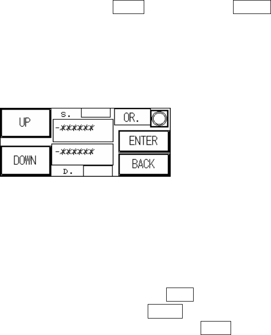
Figure 1.8 AUTO Conveyor Width Adjustment
1.3.1.4. Attention:
u All setting values have been idiot-proofed to prevent entry of negative
numbers.
u Figure 1.8 The indicator light at in the top right corner is the machine origin
Sensor. When light goes on after pressing wider button it means maximum
width has been reached. Below S. the -******* is the current conveyor
width position (unit: 0.008mm/pps); Above D. the -****** is the set
conveyor width position (unit 0.008mm/pps).
u When the conveyor width reset is in action, if there is a board to be tested
located over SENSOR1.2.3.4 then the alarm will go off and show the
Figure 1.9 display. Please remove the board before executing the Reset
operation.
u If the conveyor width operation times out before reaching the set position,
an alarm will ring and show the Figure 1.10 display. Please check the
conveyor width parts to see if they are correctly installed or malfunctioning.
u If an automatic conveyor width device is not installed and function is
accidentally triggered, this will cause a PLC Error that can not be Reset.
The PLC’s error indicator will show a red light. If this happens then the
machine power must be restarted. The PLC option must then be switched
to RUN then back to PROG, with CONV. WIDTH’s AUTO disabled and
changed to MANUAL.
7
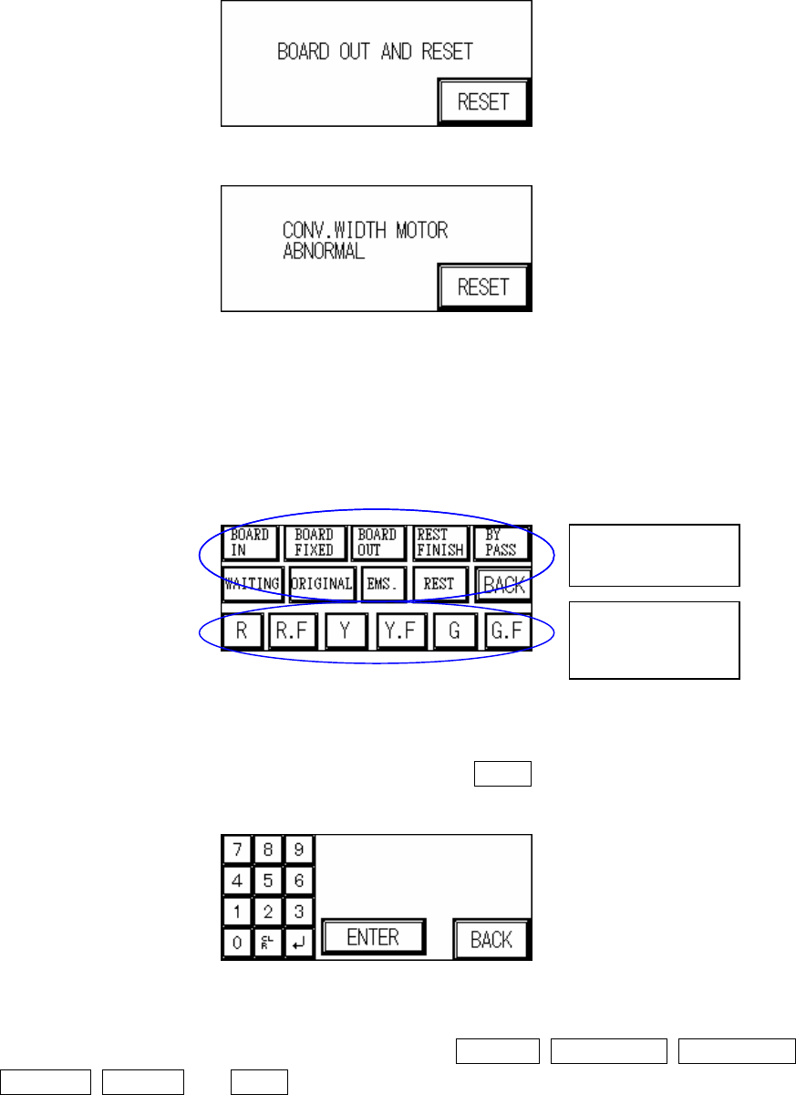
Figure 1.9 Please Remove Board
Figure 1.10 Abnormal Operation for CONV. WIDTH Motor
1.3.2 Indicator Lights (Figure 1.11): Three Colored Indicator Light Display Setting. First press to
highlight the status position to set, then select the lights to display for that step. If no
settings are made then the factory default will be used.
Figure 1.11 Indicator Lights
1.3.3 TEST COUNT: (Figure 1.12): Set the number of test cycles to perform in TEST mode. If
set as 0, then the number of cycles is infinite. Press BACK to return to the starting page
(Figure 1.1).
Figure 1.12 TEST COUNT
1.3.4 NEXT PAGE (Figure 1.13): Options available are: BUZZER, IN AND OUT, NEXT PAGE,
UP PAGE, BYPASS and BACK.
Status Position
Indicator Lights
to Display
8
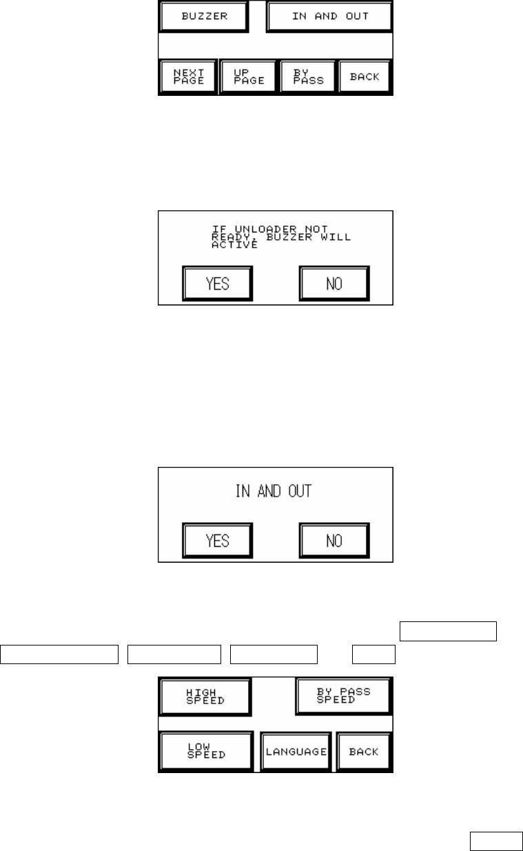
Figure 1.13 Setting – Page 2
1.3.4.1. BUZZER (Figure 1.14): Confirm if an alarm buzzer will sound to warn the operator if the
Unloader is not ready to avoid causing a board blockage at the Loader.
Figure 1.14 BUZZER
1.3.4.2. IN AND OUT (Figure 1.15): If you choose simultaneous In and Out a board can be
unloaded while another one is loaded (the test board length must be less than 200mm or
there may be an issue with board overlap); if NO is chosen then a board must be fully
unloaded before another is loaded.
Figure 1.15 IN AND OUT
1.3.4.3. NEXT PAGE (Figure 1.16): The five options available are: HIGH SPEED,
BYPASS SPEED, LOW SPEED, LANGUAGE and BACK.
Figure 1.16 Setting – Page 3
1.3.4.3.1. HIGH SPEED (Figure 1.17): This is the normal I/O speed, press ENTER at Figure
1.17 to set this speed. The speed range has an upper limit of 2600PPS and lower
limit of 100PPS.