TR7500_Hardware_en.pdf - 第64页
63 6 . 5 . 3 . 1 L O AD E R P O R T1 = U P L I N E : Y 1 04 - B l a c k ( 1 ) / G r een ( 2 ) - > R e a d y : X 8 A - R e d ( 3 ) / B l u e ( 4 ) --- - - - - > B o a r d a v a i l a b l e : X 8 B - Y e l l o w ( 5 …
62
l Holder Motor: Unfasten the four screws on the top of the motor and remove the cover.
Unfasten the screw securing the spring inside the cover and remove the spring. Now
unfasten the four screws around the motor and detach the wire connected to the machine.
The motor can now be removed.
6.5 INLINE
l INLINE PORT: First check to see if it’s the front or back stage that has the problem.
6.5.1 Does Not Load
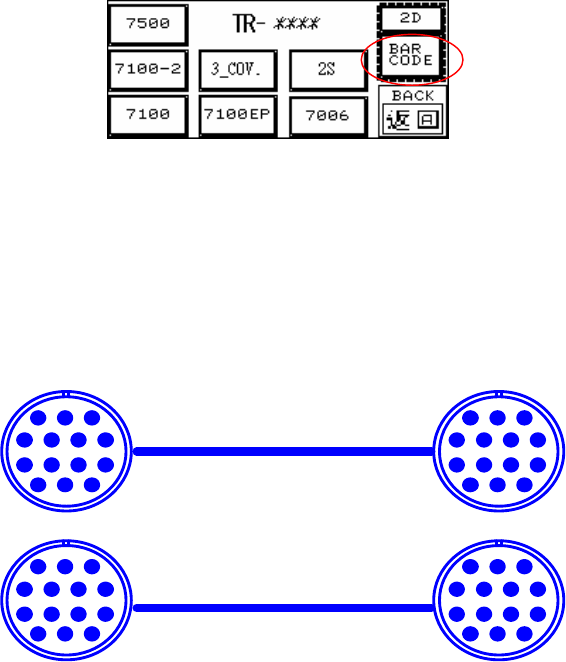
l LOADER: First highlight the BAR CODE, and if board can now be loaded that means there’s
a problem with the Barcode settings in the main program. If board still can’t be loaded this
indicates a problem with the wiring.
l Inspect the Barcode Setting-Barcode Button (Disable/Enable): Highlight so the main
program will not examine the barcode (don’t wait for signal from main program on PC for
loading); Clear the highlight if it is to be examined (wait for signal from main program on PC
for before loading). This option works the same way for 1D or 2D Barcode settings.
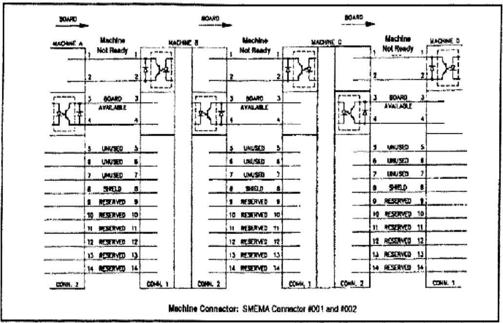
l Check that the Loader Wiring is Correct (As Figure Below)
6.5.2 Does Not Unload Unloader
l Unloader Not Ready
l Check that the Unloader Wiring is Correct (As Figure Below):
6.5.3 Signal Meaning
PIN1~PIN6
123
4567
891011
121314
PIN1~PIN6
123
4567
891011
121314
123
4567
891011
121314
123
4567
891011
121314
63
6.5.3.1 LOADER
PORT1=UP LINE : Y104-Black(1) / Green (2) ->Ready
: X8A-Red(3) / Blue(4) ------->Board available
: X8B-Yellow (5)/ White(6) ->Spare
l Located below the power supply socket in the back of the equipment is I/O PORT1. Connect
the connector, and there are three sets of different colored wire pairs at the connector end.
These are: Black-Green (Y104) for requesting board from Loader, Red-Blue (X8A) reserved
INPUT connector and the Yellow-White (X8B) reserved INPUT connector. Connect the
Black-Green connector to the Loader Board Request connection. (We use the standard
SMEMA signal. If this is different due to differences in manufacturer, contact the front stage
manufacturer to acquire the connection data.)
6.5.3.2 UNLOADER
PORT2=DOWN LINE : X98-Black(1) / Green(2) --> Ready
: Y106-Red(3) / Blue(4) --> Board available
: Y105-Yellow(5) / White(6)--> (OK: Short ; NG: Open)
l Located below the power supply socket in the back of the equipment is I/O PORT2. Connect
the connector, and there are three sets of different colored wire pairs at the connector end.
These are: Black-Green (X98) for receiving READY board request signal from the Unloader,
Red-Blue (Y106) board unload signal to the Unloader and the Yellow-White (Y105) TEST
PASS signal connector. Connect the Black-Green connector with the Unloader’s connector
for sending READY board request signal. Then connect the Yellow-White connector with the
Unloader TEST PASS signal receiving signal. (We use the standard SMEMA signal. If this is
different due to differences in manufacturer, contact the front stage manufacturer to acquire
the connection data.)
l EXPLAIN
GO IN TRI-PORT1
Y 104 ( OUT ) Main station request to insert board could be used as " not busy "
X8A ( IN ) missing in documentation!!! "board available"
GO OUT TRI-PORT2
X98 ( IN ) Backward station READY could be used as " not busy"
Y106 ( OUT ) missing in documentation!!! "board available"
Y105 ( Out ) TEST OK "pass"
64
l The standard SMEMA signal link is as shown in figure below.