YSM20_YSM20W_Mainte_E.pdf - 第174页
A-1 Appendix 1. Specifications 1.1 Air regulator unit T he regulator that regulates the air pressure supplied to the air drive section of this machine is located behind the front lower left panel of the main unit. Specif…

A-1
Appendix
1. Specifications
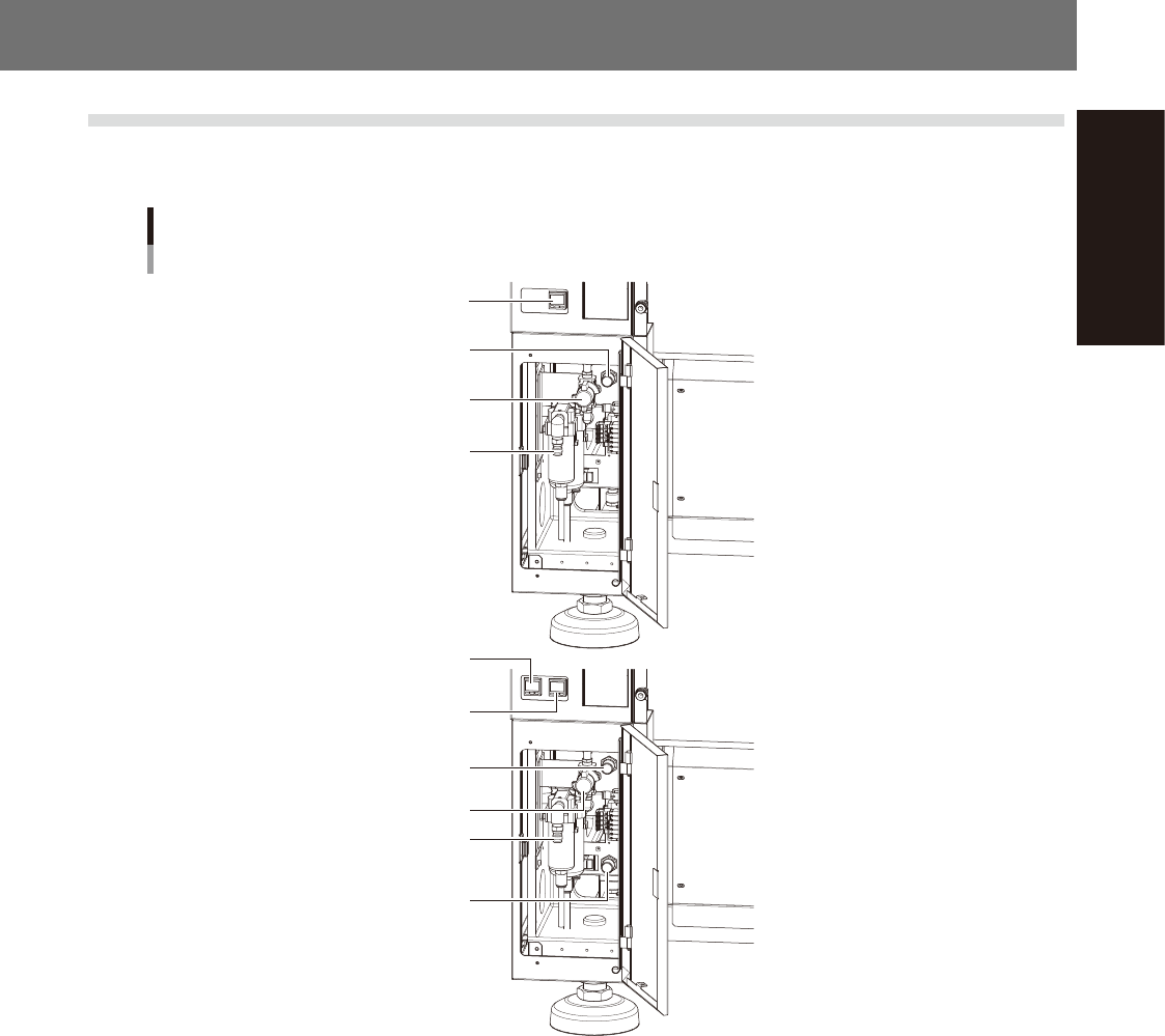
1.1 Air regulator unit
The regulator that regulates the air pressure supplied to the air drive section of this machine is located behind
the front lower left panel of the main unit. Specify the appropriate air pressure setting shown below.
Air pressure regulator and pressure gauge
For 1-beam
For 2-beam
Air supply/exhaust switch
Source air connector
Air pressure regulator
Digital pressure gauge
Digital pressure gauge
(A-table)
Digital pressure gauge
(B-table)
Air supply/exhaust switch
Source air connector
Air pressure regulator
(A-table)
Air pressure regulator
(B-table)
53A01-N2-00
n
Supply air pressure
This is the pressure of the source air supplied to the machine. Before setting the air pressure with the air regulator, make
sure that this supply air pressure is in the following optimal range.
Z:LEX (YSM20, YSM20W) : 0.45MPa to 0.70MPa
n
Digital pressure gauge
When within the normal range, the air pressure displays in green. When the air pressure is beyond the upper/lower limit
values (air down detection), an error occurs, and the air pressure displays in red.
n
Set pressure and air-down detection pressure
Air pressure setting for machine : 0.40MPa (±0.01)
(When the air pressure reaches 0.45MPa, the air pressure display turns red.)
Pressure-drop detection level : 0.33MPa
n
Air supply/exhaust switch (valve)
Turning this switch to the right shuts off air supply and exhausts air that remains inside the machine.
n
Source air connector
Prepare an air hose with an inner diameter of at least 8 mm having a 40SH socket (Nitto Koki, or equivalent), and
connect it to this connector. Use dry, clean air passed through an air filter.
A-2
Appendix
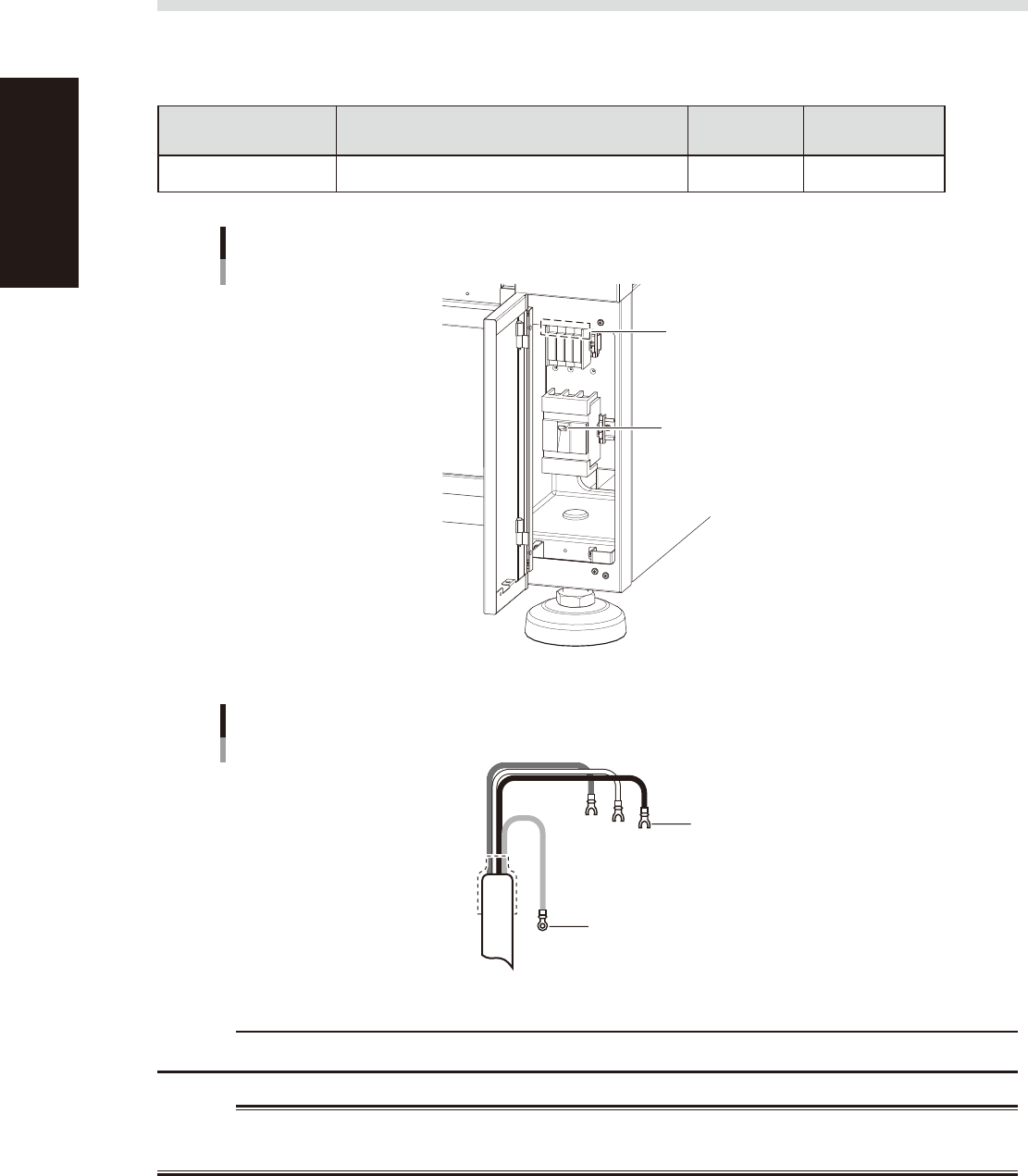
1.2 Power connection terminals
When opening the front lower right panel, you can find the power connection terminals. Connect the power
cable leads as shown below to the L1, L2, L3 and ground terminal (PE) on the power terminal block.
n
Power supply specifications
Model name Power
Frequency
Power
capacity
Z:LEX(YSM20,YSM20W) 3-phase AC 200/208/220/240/380/400/416V(±10%) 50/60Hz 13.9kVA
Power input terminals (L1, L2, L3)
and ground terminal
Main breaker
Power connection terminals
53A02-N2-00
Ring-tongue crimp terminal
Insulated crimp terminal
Power cable
L2
L1
L3
L=100
PE
53A03-N2-00
c
CAUTION
Use a power cable whose conductor cross-section area is greater than 10 mm
2
.
w
WARNING
TO AVOID THE RISK OF ELECTRICAL SHOCK, MAKE SURE THAT THE POWER SOURCE IS OFF BEFORE CONNECTING THE
POWER CABLE. ALSO MAKE SURE THAT THE GROUND CABLE IS SECURELY CONNECTED TO THE MACHINE.