Maintenance Manual.pdf - 第74页
AV131 MAINTENANCE MANUAL 4.1 Cont rol Sy ste m Confi guration D79MEC- 14-020-A0 4.1- 3 4.1. 3 P9 General Description P9 i s a s i ngl e CPU system c ontroll er f eat uring a 32-bit mic rocomputer . Board Configuratio…
AV131
MAINTENANCE MANUAL
4.1 Control System Configuration
D79MEC-14-020-A0
4.1-2
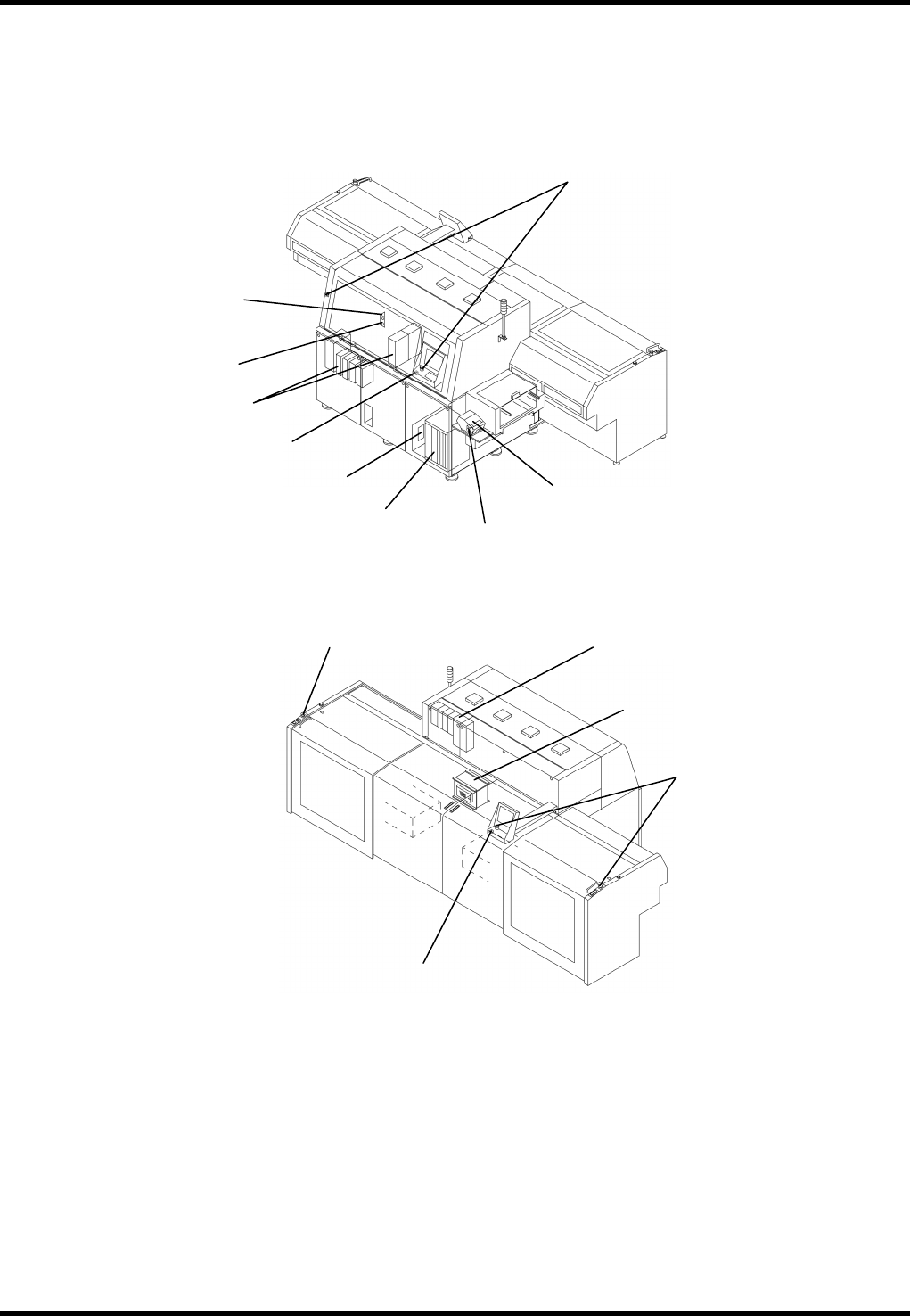
4.1.2 Control Unit Arrangement
Front
Rear
Maintenance switch
Emergency stop switch
AC servomotor driver
Pulse motor driver
Enabling switch
Printer
Main switch
Main controller
Enabling switch
Emergency stop switch
Emergency stop switch
Transformer box
AC servomotor driver
Enabling switch
AV131
MAINTENANCE MANUAL
4.1 Control System Configuration
D79MEC-14-020-A0
4.1-3
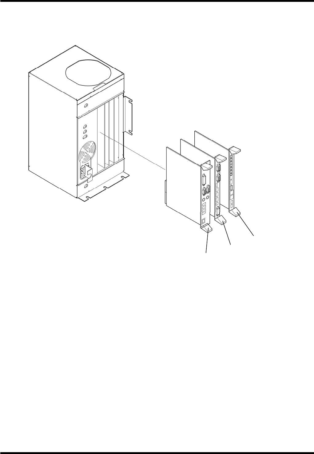
4.1.3 P9
General Description
P9 is a single CPU system controller featuring a 32-bit microcomputer.
Board Configuration
P9 consists of the following boards:
0.
1. PCB-COM board
Model: NBC-JC134X-D
Function: PCB-COM board controls interface with exterior devices.
2. Camera interface board
Model: PPRCAC-AA
Function: The component insertion hole data from the CCD camera is written into the memory and
calculated in comparison to the previously determined standard hole position.
3. Axis and I/O control board
Model: PNFCAA-AA
Function: The board sends signals to AC servo drivers according to values set in the NC program in
order to control AC servomotors.
1.
2.
3.
AV131
MAINTENANCE MANUAL
4.1 Control System Configuration
D79MEC-14-020-A0
4.1-4
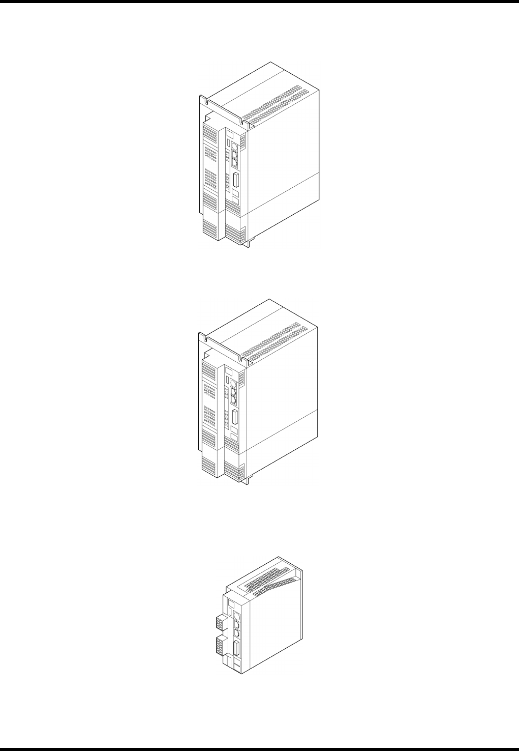
4.1.4 Driver
MFDDTA390N01 (For H axis)
MFDDTB3A2N01 (For θH, ZL (Exclusive for 120 inputs) and ZR axes)
MCDDT3520N01 (For Y, T and θA axes)