Maintenance Manual.pdf - 第92页
AV131 MAINTENANCE MANUAL 4.1 Cont rol Sy ste m Confi guration D79MEC- 14-020-A0 4.1- 21 I / O M AP O UTPUT Board conne ct or Address No. Name bi t Not e 49 00300 : I nserti on volt age check 1: OUT 0 50 00301 : I nserti …
AV131
MAINTENANCE MANUAL
4.1 Control System Configuration
D79MEC-14-020-A0
4.1-20
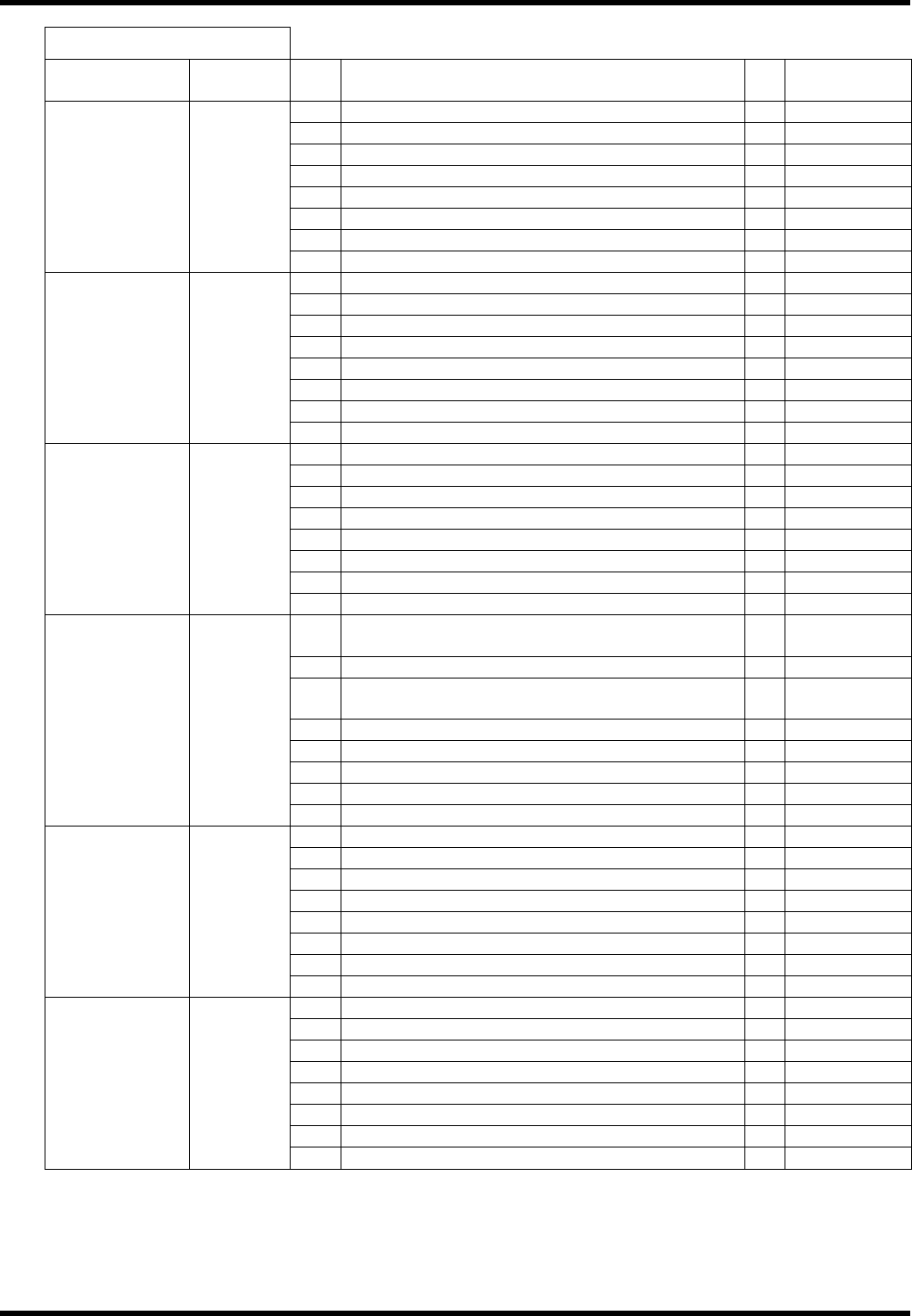
I / O MAP OUTPUT
Board
connector
Address No. Name bit Note
1 04200: Right rail forward valve OUT 0
2 04201: Right rail reverse valve: OUT 1
3 04220: Right belt motor right turn: OUT 2
4 04221: Right belt motor reverse turn: OUT 3
5 00324: Safety stop support valve: OUT 4
6 5
7 6
#0_CN5 0020
8 7
9 0
10 1
11 Recognition light source ON 2
12 Recognition light source ON 3
13 Recognition light source ON 4
14 5
15 6
#0_CN7 0021
16 7
17 04205: PCB position right: OUT (OP) 0 Option
18 1
19 2
20 3
21 00316: PCB supply valve: OUT (OP) 4 Option
22 04216: PCB stopper 1 valve: OUT (OP) 5 Option
23 6
#0_CN9 0022
24 7
25
00306: ZR axis parts changing lamp output:
OUT
0
26 00321: ZR axis parts changing signal: OUT 1
27
00305: ZL axis parts changing lamp output:
OUT
2
28 00320: ZL axis parts changing signal: OUT 3
29 4
30 5
31 6
#0_CN6 0023
32 7
33 04202: Left rail forward valve 0
34 04203: Left rail reverse valve: OUT 1
35 04222: Left belt motor right turn: OUT 2
36 04223: Left belt motor reverse turn: OUT 3
37 04204: Positioner lever valve: OUT 4
38 5
39 6
#1_CN5 0060
40 7
41 04210: Inverter forward signal: OUT 0
42 04211: Inverter reverse signal: OUT 1
43 04212: Inverter speed command 1: OUT 2
44 04213: Inverter speed command 2: OUT 3
45 04214: Inverter abnormal reset: OUT 4
46 04215: Transfer brake release: OUT 5
47 6
#1_CN7 0061
48 7
AV131
MAINTENANCE MANUAL
4.1 Control System Configuration
D79MEC-14-020-A0
4.1-21
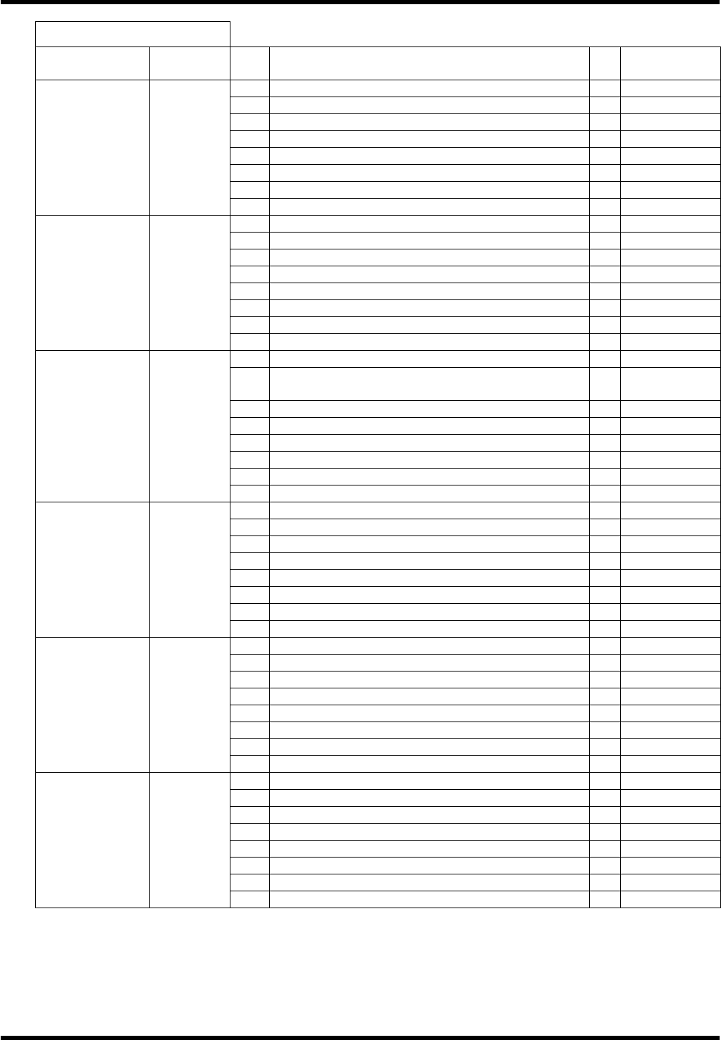
I / O MAP OUTPUT
Board
connector
Address No. Name bit Note
49 00300 : Insertion voltage check 1: OUT 0
50 00301 : Insertion voltage check 2: OUT 1
51 : Insertion voltage check 3: OUT 2
52 3
53 4
54 5
55 6
#1_CN9 0062
56 7
65 04206: P.PUSH (Traverse) valve: OUT 0
66 04207: P.PUSH (Return) valve: OUT 1
67 2
68 3
69 4
70 5
71 6
#1_CN8 0064
72 7
73 00207: Air blow valve: OUT 0
74
00217: T axis position / H axis brake release
detection: OUT
1
75 00224: H axis brake release output: OUT 2
76 00225: T axis normal position output: OUT 3
77 00227: T axis origin signal: OUT 4
78 5
79 6
#2_CN5 00A0
80 7
89 00210: Rotary chuck 1 valve: OUT 0
90 00211: Rotary chuck 2 valve: OUT 1
91 00212: Rotary chuck 3 valve: OUT 2
92 00213: Rotary chuck 4 valve: OUT 3
93 00214: 26 slide chuck valve: OUT 4
94 00215: 52 slide chuck valve: OUT 5
95 00216: Slide chuck pitch switch valve: OUT 6
#2_CN6 00A3
96 7
97 00220: JW set valve (Traverse): OUT 0
98 00221: JW set valve (Return): OUT 1
99 00222: Chuck slide valve (Traverse): OUT 2
100 00223: Chuck slide valve (Return): OUT 3
101 00226: Tape cutter damper valve: OUT 4
102 5
103 6
#2_CN8 00A4
104 7
105 00200: Warning lamp (Red / Yellow): OUT 0
106 00201: Warning lamp (Yellow / White): OUT 1
107 00202: Warning lamp (Green): OUT 2
108 00206: Buzzer output: OUT (OP) 3 Option
109 Origin display LED 4
110 5
111 6
#3_CN5 00E0
112 7
AV131
MAINTENANCE MANUAL
4.1 Control System Configuration
D79MEC-14-020-A0
4.1-22
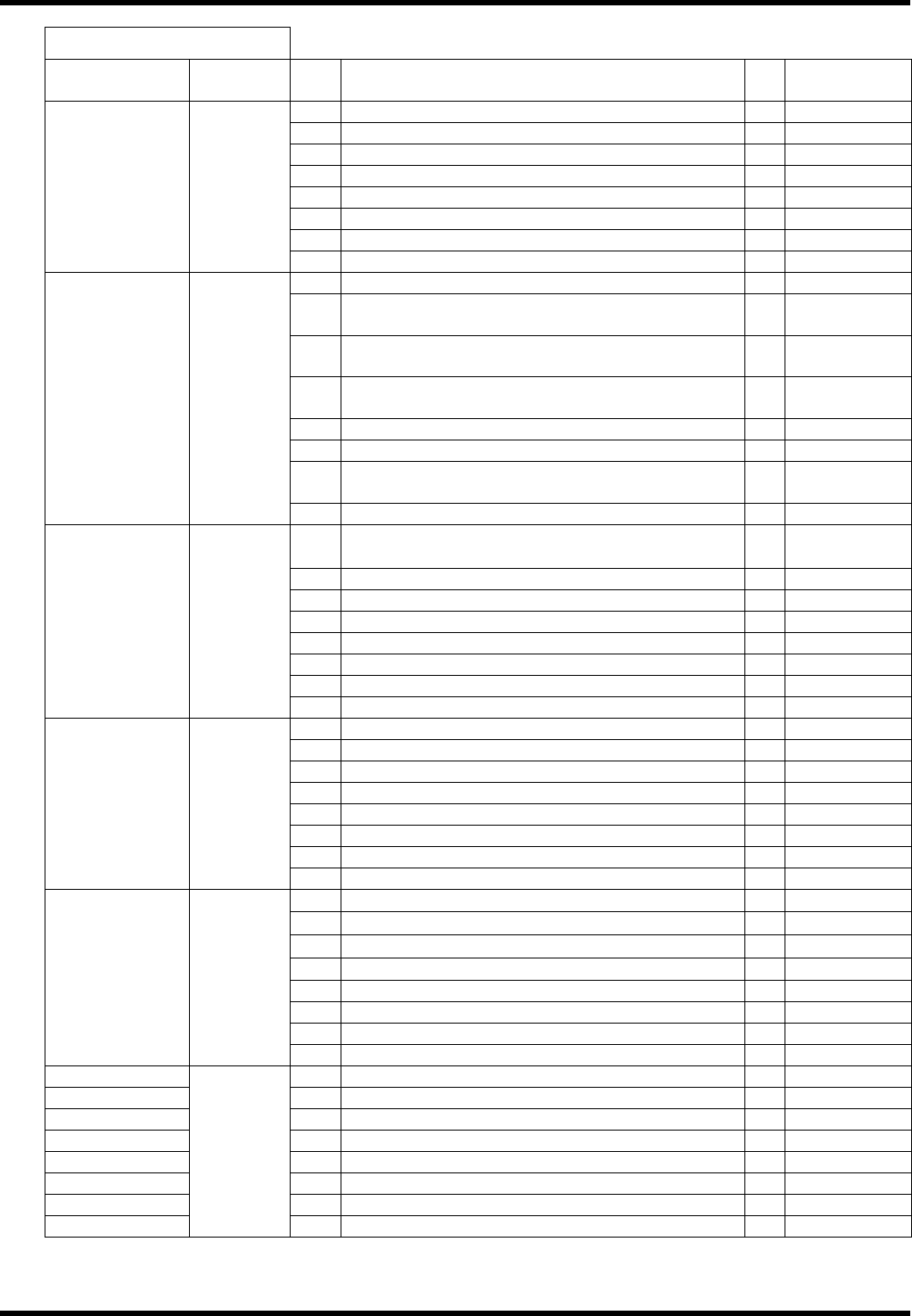
I / O MAP OUTPUT
Board
connector
Address No. Name bit Note
113 00302: Part waste blow valve: OUT 0 Option
114 1
115 2
116 3
117 4
118 5
119 6
#3_CN7 00E1
120 7
137 04230: Rail open/close valve (BSF-V): OUT 0
138
04231: PCB conveyor motor reverse return
(BSF-V): OUT
1
139
04232: PCB conveyor motor right return
(BSF-V): OUT
2
140
04233: PCB conveyor motor brake (BSF-V):
OUT
3
141 04234: Vacuum valve (BSF-V): OUT 4
142 04235: Vacuum suction valve up (BSF-V): OUT 5
143
04236: Vacuum suction valve down (BSF-V):
OUT
6
#4_CN5 0120
144 7
145
03334: Automatic width adjustment start signal
(SC → CONV): OUT (OP)
0 Option
146 1
147 2
148 3
149 4
150 5
151 6
#4_CN7 0121
152 7
153 04256: Conveyor belt motor signal: OUT (OP) 0 Option
154 1
155 2
156 3
157 4
158 5
159 6
#4_CN9 0122
160 7
161
Group empty signal (SC → LM)
0
162
Loader empty signal (SC → LM)
1
163
Count up signal (SC → LM)
2
164
Main body empty signal (SC → LM)
3
165 4
166 5
167 6
#4_CN6 0123
168 7
#22_CNMC3 329 Vacuum pump ON 0
#22_CNMC2 330 1
#22_Inside 331 Main circuit ON 2
#22_CNBK1 332 3
#22_CNBK2 333 4
#22_Inside 334 Safety relay reset 5
#22_Inside 335 Motor 24V power ON 6
#22_Inside
00A0
336 Instantaneous stop detection reset 7