Maintenance Manual.pdf - 第84页
AV131 MAINTENANCE MANUAL 4.1 Cont rol Sy ste m Confi guration D79MEC- 14-020-A0 4.1- 13 Func ti on Error code N o. Cause Co untermeasu re ID s ettin g error 82 The I D setting v a l ue is outside t he range 0 t o 31. Che…

AV131
MAINTENANCE MANUAL
4.1 Control System Configuration
D79MEC-14-020-A0
4.1-12
Function
Error
code No.
Cause Countermeasure
* External
scale status
0 error
50
The bit 0 for the error code (ALMC)
of the external scale changed to 1.
Check the specifications of the
external scale
* External
scale status
1 error
51
The bit 1 for the error code (ALMC)
of the external scale changed to 1.
Check the specifications of the
external scale
* External
scale status
2 error
52
The bit 2 for the error code (ALMC)
of the external scale changed to 1.
Check the specifications of the
external scale
* External
scale status
3 error
53
The bit 3 for the error code (ALMC)
of the external scale changed to 1.
Check the specifications of the
external scale
* External
scale status
4 error
54
The bit 4 for the error code (ALMC)
of the external scale changed to 1.
Check the specifications of the
external scale
* External
scale status
5 error
55
The bit 5 for the error code (ALMC)
of the external scale changed to 1.
Check the specifications of the
external scale
Eliminate the cause of the error and clear
the error of the external scale. Then turn
the control power OFF once and turn it
back ON. Check the specifications of the
external scale concerning the causes of the
errors.
Origin return
error
68
An error occurred during origin
return. Abnormal inhibit input signal
was entered. Parameters required for
origin return have not been set or
invalid values have been set.
Check for abnormality in the switch, limit
sensor, wires and power supply to be
connected to the inhibit inputs (CCWL,
CWL: CN X5 19, 20 pin).
Check the parameters related to the origin
return.
Data
undefined
error
69
Parameters required for the
commanded step or jog movement
have not been set, or invalid values
have been set.
Check the settings of positioning and step
parameters.
Current
position
overflow
70
When the 16.Pr51 (wrap-around
permit) is 0, the current position
(-2147483647 to 2147483647)
overflowed.
Do not send such an operation command
as the current position outside
-2147483647 to 2147483647.
Take particular care for incremental
movement, jog or origin offset.
Drive inhibit
input
detection
error
71
During step or jog movement after
origin return, drive inhibit input for the
moving direction was detected.
Both of the drive inhibit inputs
(CCWL, CWL: CN X5, Pins #19 and
#20) opened.
Check the switches and limit sensors
connected to the drove inhibit input and
wiring or power supply for any problem.
Check the operation command and
installation of the limit sensor.
Check if the direction of origin offset
coincides with that of the drive inhibit input.
* Max. travel
limit error
72
The command position of the motor
exceeded the maximum travel limit
range in the step or jog mode after
origin return.
Make sure there is no positional command
that exceeds the maximum travel limit. Take
particular care for incremental movement,
jog or origin offset.
Check the setting values of 32.Pr01 (max.
travel in positive direction) and 32.Pr02
(max. travel in negative direction).
AV131
MAINTENANCE MANUAL
4.1 Control System Configuration
D79MEC-14-020-A0
4.1-13
Function
Error
code No.
Cause Countermeasure
ID setting
error
82
The ID setting value is outside the
range 0 to 31.
Check the setting of the rotary switch on
the front panel.
* External
scale
automatic
recognition
error
93
Inapplicable external scale is
connected.
Replace the applicable external scale.
* Motor
automatic
recognition
error
95
The motor and servo amplifier do not
match.
Replace the motor that matches the servo
amplifier.
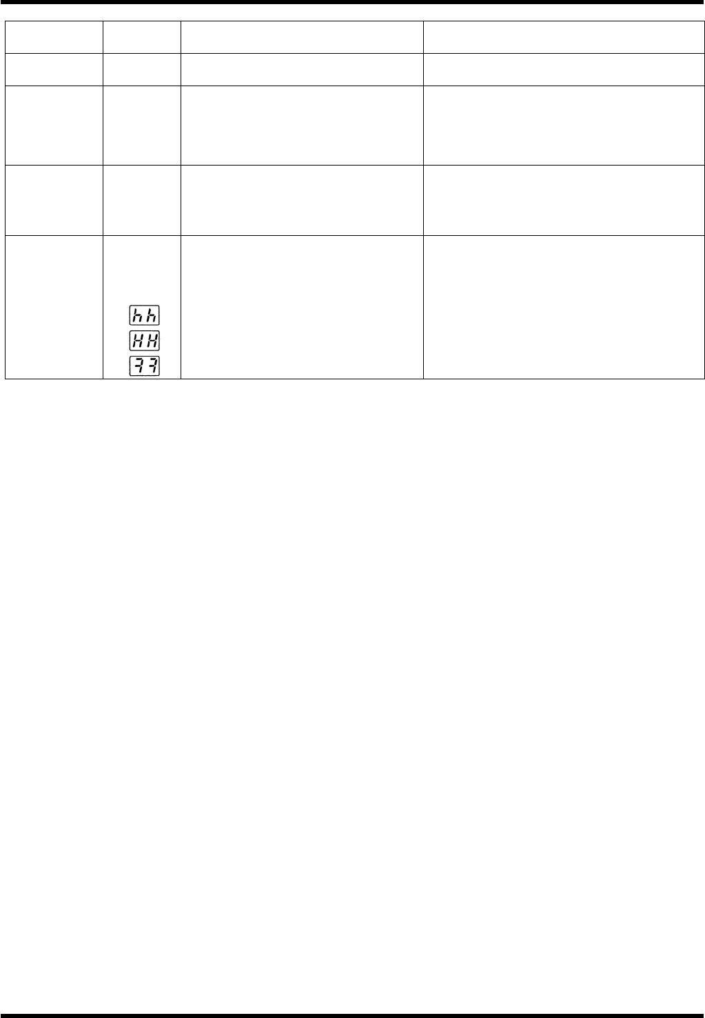
Other error
Other
number
may be
shown.
Control circuit malfunctioned due to
excessive noise, etc. The
self-diagnosis function of the servo
amplifier worked to indicate some
kind of trouble occurred in the servo
amplifier.
Turn power OFF once and turn it back ON.
If the error persists, the motor and servo
amplifier may be defective.
When this happens, stop the operation and
replace them.
Consult with the dealer for inspection
(repair).
=REMARKS=
The protective functions marked with an asterisk (∗) below the alarm codes cannot be cleared. Shut
OFF all power sources once and reset the alarm.
AV131
MAINTENANCE MANUAL
4.1 Control System Configuration
D79MEC-14-020-A0
4.1-14
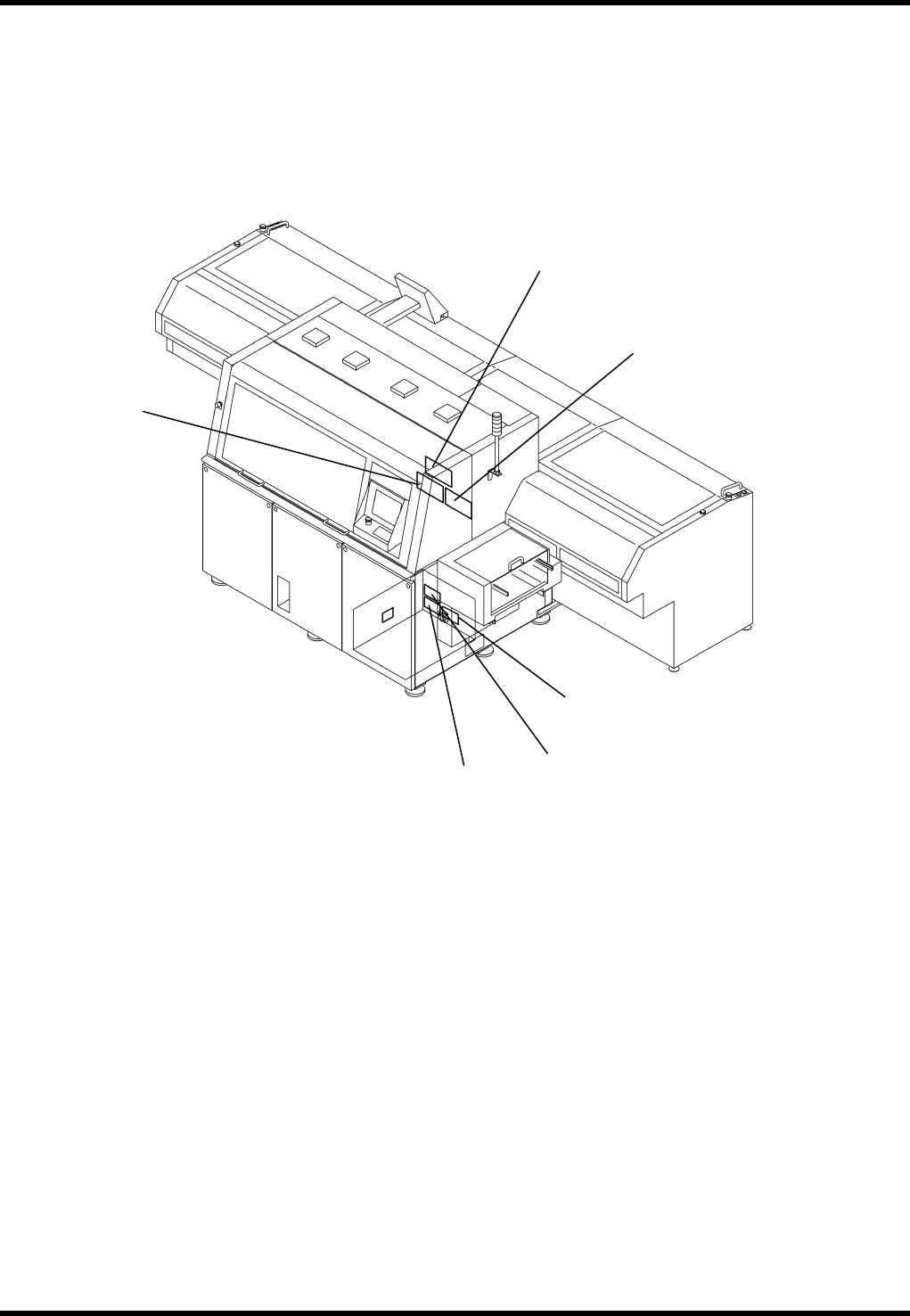
4.1.5 Ring I/O Load Board Arrangement
5.
6. (OPTION)
4.
3.
2.
1.