Maintenance Manual.pdf - 第85页
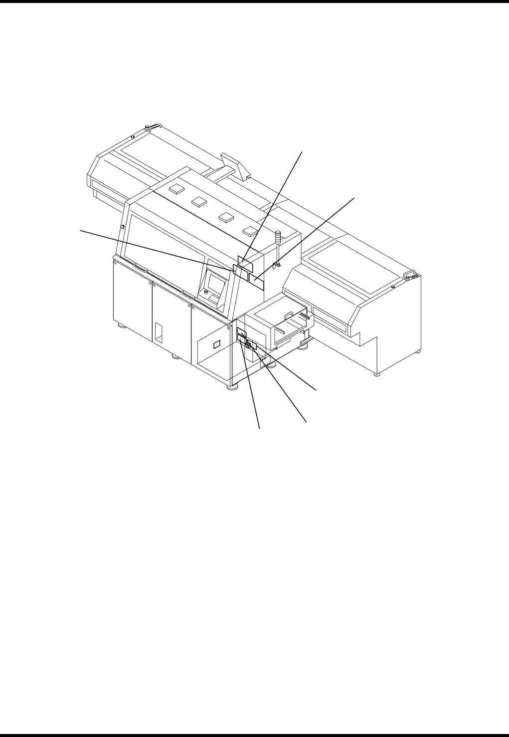
AV131 MAINTENANCE MANUAL 4.1 Cont rol Syst e m Confi guration D79MEC- 14-020-A0 4.1- 14 4.1.5 Ring I/O Loa d Boar d A rrangement 5. 6. (O P TION) 4. 3. 2. 1.
AV131
MAINTENANCE MANUAL
4.1 Control System Configuration
D79MEC-14-020-A0
4.1-13
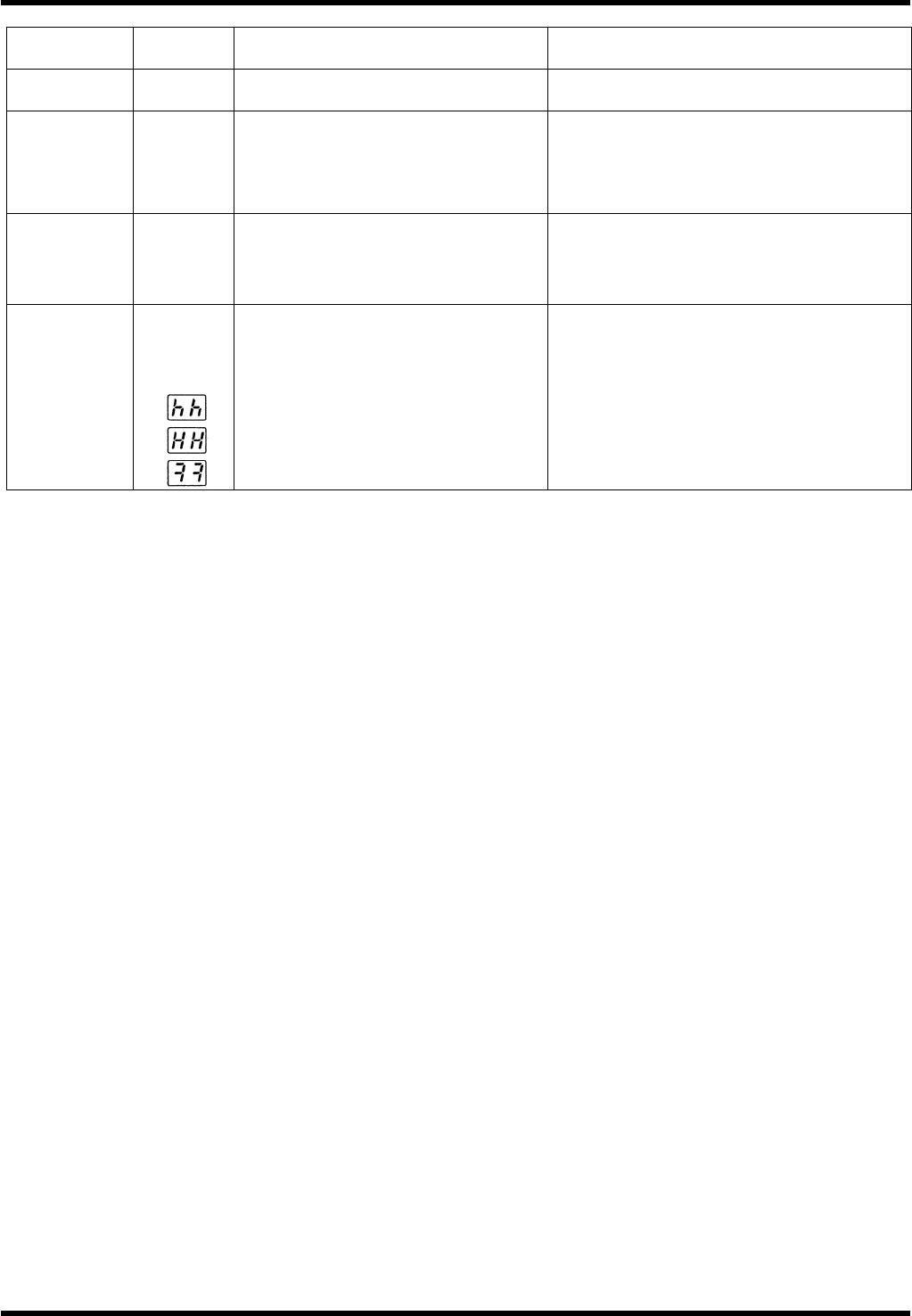
Function
Error
code No.
Cause Countermeasure
ID setting
error
82
The ID setting value is outside the
range 0 to 31.
Check the setting of the rotary switch on
the front panel.
* External
scale
automatic
recognition
error
93
Inapplicable external scale is
connected.
Replace the applicable external scale.
* Motor
automatic
recognition
error
95
The motor and servo amplifier do not
match.
Replace the motor that matches the servo
amplifier.
Other error
Other
number
may be
shown.
Control circuit malfunctioned due to
excessive noise, etc. The
self-diagnosis function of the servo
amplifier worked to indicate some
kind of trouble occurred in the servo
amplifier.
Turn power OFF once and turn it back ON.
If the error persists, the motor and servo
amplifier may be defective.
When this happens, stop the operation and
replace them.
Consult with the dealer for inspection
(repair).
=REMARKS=
The protective functions marked with an asterisk (∗) below the alarm codes cannot be cleared. Shut
OFF all power sources once and reset the alarm.
AV131
MAINTENANCE MANUAL
4.1 Control System Configuration
D79MEC-14-020-A0
4.1-14
4.1.5 Ring I/O Load Board Arrangement
5.
6. (OPTION)
4.
3.
2.
1.
AV131
MAINTENANCE MANUAL
4.1 Control System Configuration
D79MEC-14-020-A0
4.1-15
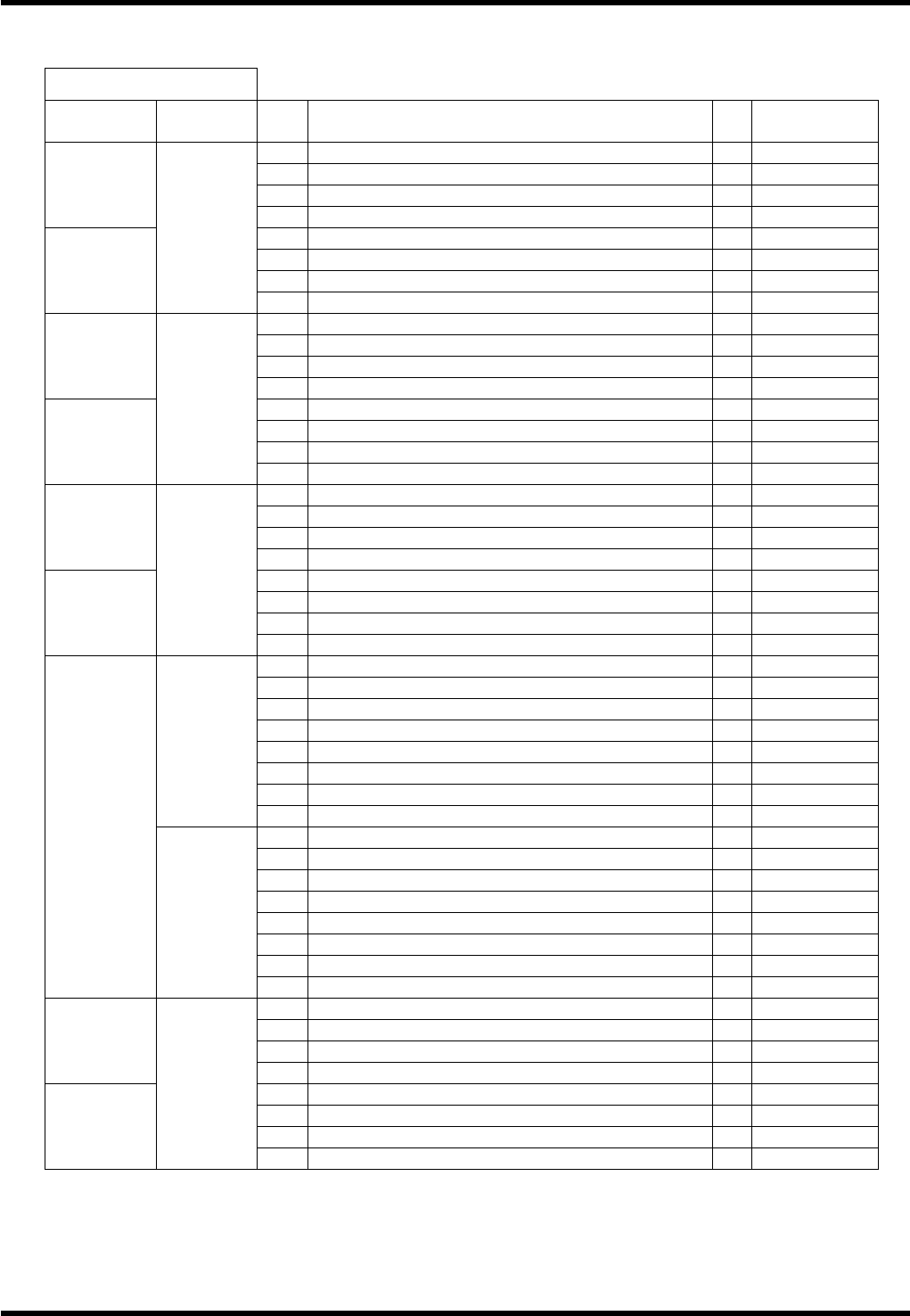
4.1.6 I/O Map
I/O MAP INPUT
Board
connector
Address No. Name bit Note
1 04020: Right rail traverse limit: IN 0
2 04021: Right rail return limit: IN 1
3 04022: PCB detection 1: IN 2
#0_CN16
4 04023: PCB detection 2: IN 3
5 04032: Carry arm return detection: IN 4
6 04033: Carry arm slow down detection: IN 5
7 04034: Carry arm traverse detection: IN 6
#0_CN15
0000
8 7
9 Main frame left side fan alarm: IN 0
10 Main frame controller fan alarm 1
11 Main frame right side fan alarm 2
#0_CN14
12 3
13 TABLE GAP DETECT (-S214) 4
14 ZR motor thermal 5
15 00116: ZR cassette gap detection: IN 6
#0_CN13
0001
16 7
17 WA AXIS ORG. 0
18 1
19 2
#0_CN12
20 3
21 04047: MLP input signal: IN (OP) 4 Option
22 00120: Air down: IN 5
23 6
#0_CN11
0002
24 7
25 04010: XY table inside PCB detection: IN 0
26 04013: Positioner error detection: IN 1
27 04016: XY table inside PCB detection 2: IN (OP) 2 Option
28 00056: 2 PCB transfer: IN (OP) 3 Option
29 04014: Positioner lever traverse limit: IN 4
30 04015: Positioner lever return limit: IN 5
31 6
0003
32 7
33 X AXIS+LIMIT 0
34 X AXIS ORG. 1
35 X AXIS-LIMIT 2
36 3
37 Y AXIS+LIMIT 4
38 Y AXIS ORG. 5
39 Y AXIS-LIMIT 6
#0_CN10
0004
40 7
41 Cover LEFT SIDE AT FRONT COVER (-S303) 0
42 1
43 04006: Push arm / push up traverse limit: IN 2
#1_CN16
44 04007: Push arm / push up return limit: IN 3
45 04000: Left rail traverse limit: IN 4
46 04001: Left rail return limit: IN 5
47 04002: PCB detection 3: IN 6
#1_CN15
0040
48 04003: PCB detection 4: IN 7