Maintenance Manual.pdf - 第90页
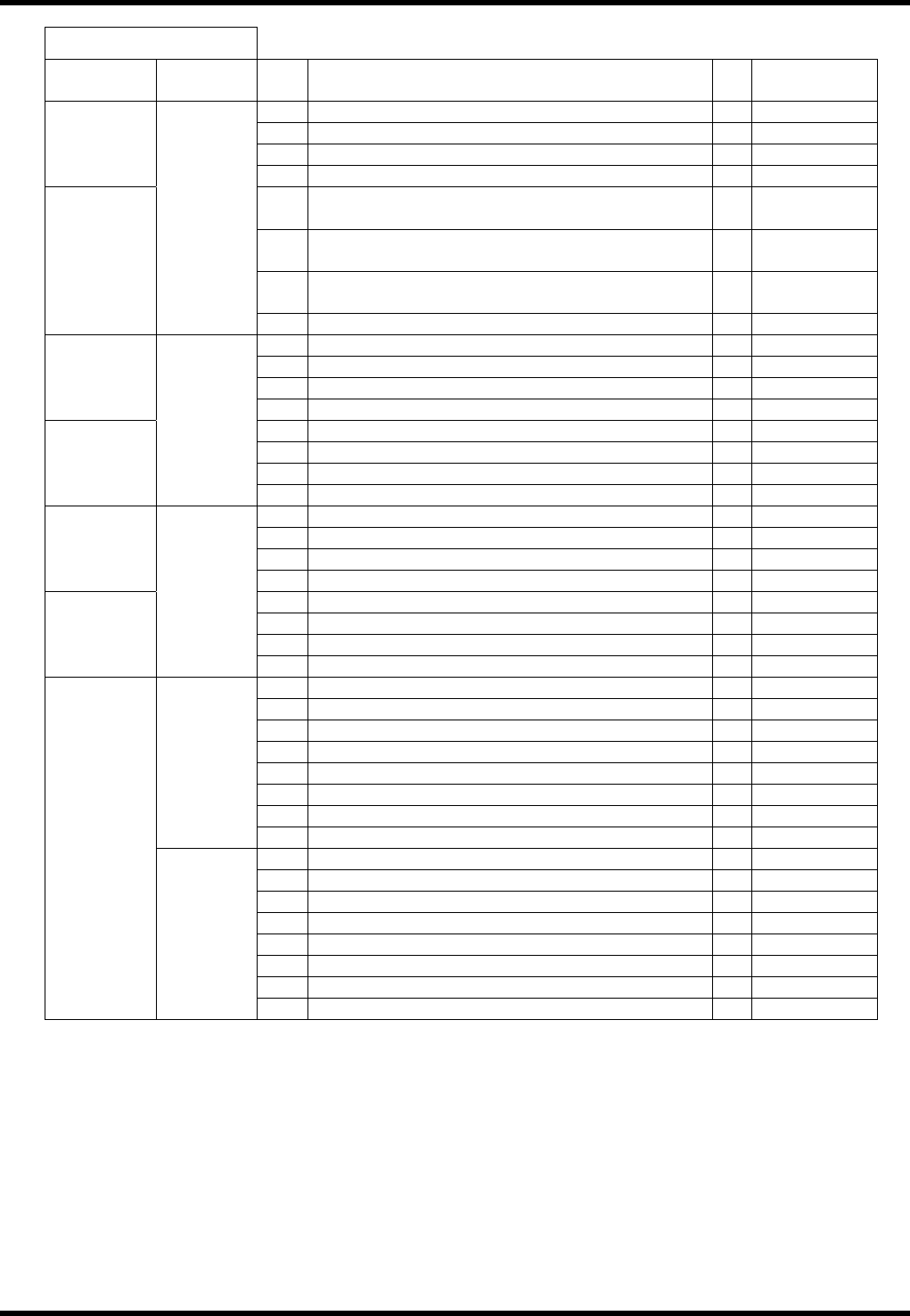
AV131 MAINTENANCE MANUAL 4.1 Cont rol Sy ste m Confi guration D79MEC- 14-020-A0 4.1- 19 I / O M AP I NPUT Board conne ct or Address No. Name bi t Not e #22_CNMC2 441 Therm al 1 (Vac uu m pum p) 0 #22_CNMC3 442 Therm al 2…
AV131
MAINTENANCE MANUAL
4.1 Control System Configuration
D79MEC-14-020-A0
4.1-18
I / O MAP INPUT
Board
connector
Address No. Name bit Note
153 04026: PCB supply traverse limit: IN (OP) 0 Option
154 04027: PCB supply return limit: IN (OP) 1 Option
155 2 Option
#4_CN16
156 3
157
00155: Automatic width adjustment completion
signal (SC → CONV): IN (OP)
4 Option
158
04056: Width adjustment interlock (R side): IN
(OP)
5 Option
159
04057: Width adjustment interlock (L side): IN
(OP)
6 Option
#4_CN15
0100
160 7
161 0
162 1
163 2
#4_CN14
164 3
165 CVT check 1 4
166 CVT check 2 5
167 6
#4_CN13
0101
168 Unloader option PCB no signal 7
169 0
170 1
171 2
#4_CN12
172 3
173 Loading inhibition signal 4 Option
174 Empty signal (R) 5 Option
175 Empty signal (L) 6 Option
#4_CN11
0102
176 7
177 04040: Vacuum upper limit (BSF-V): IN 0 Option
178 04041: Vacuum lower limit (BSF-V): IN 1 Option
179 04042: PCB vacuum detection (BSF-V): IN 2 Option
180 04043: PCB carry traverse limit (BSF-V): IN 3 Option
181 04044: PCB carry return limit (BSF-V): IN 4 Option
182 04045: BSF PCB detect limit (BSF-V): IN 5 Option
183 04046: Safety cover SW (BSF-V): IN 6 Option
0103
184 04050: VACUUM SW (BSF-V): IN 7 Option
185 04051: UP SW (BSF-V): IN 0 Option
186 04052: DOWN SW (BSF-V): IN 1 Option
187 04053: Rail open/close SW (BSF-V): IN 2 Option
188 04054: FOWARD SW (BSF-V): IN 3 Option
189 04055: REVERSE SW (BSF-V): IN 4 Option
190 5
191 6
#4_CN10
0104
192 7
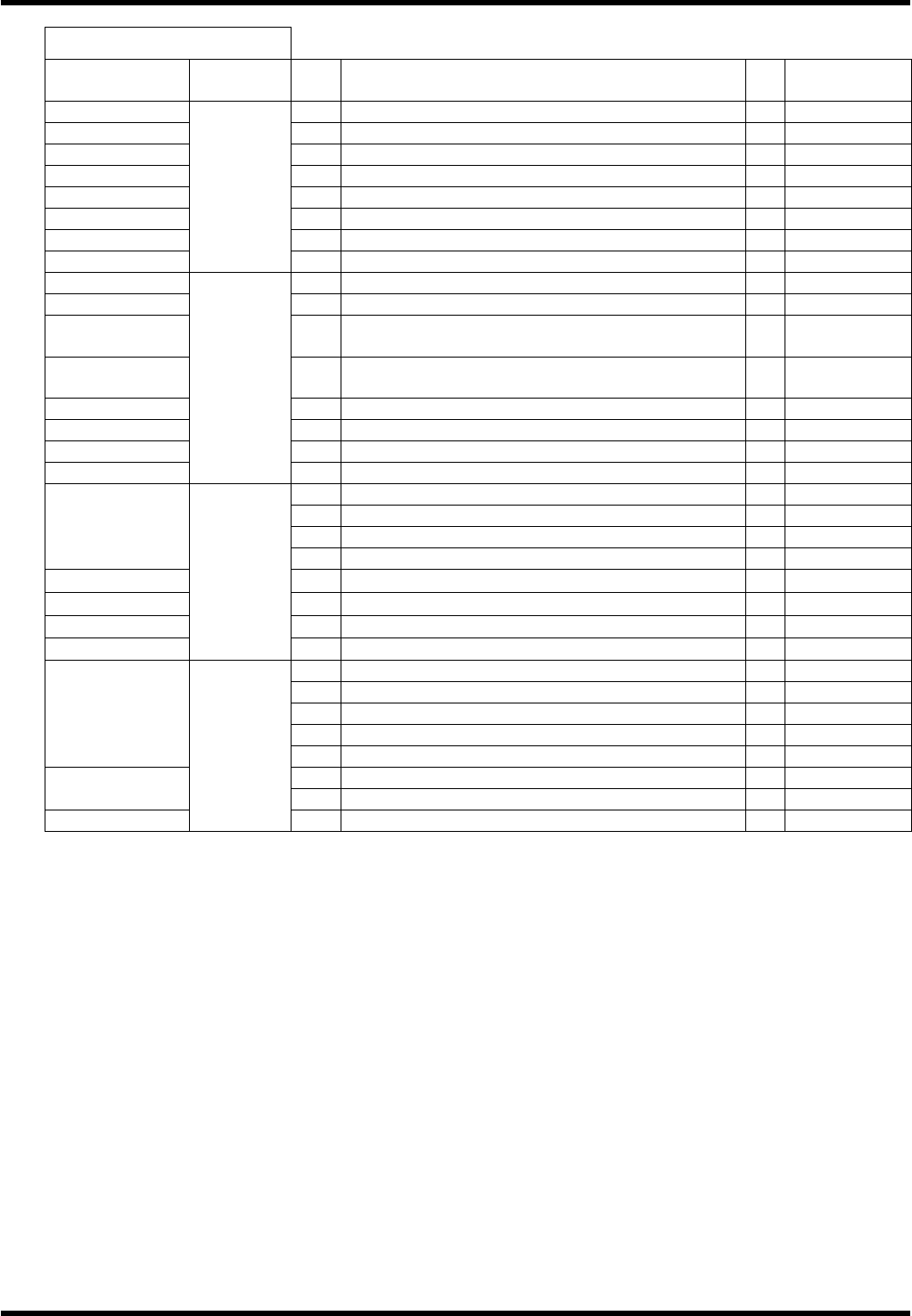
AV131
MAINTENANCE MANUAL
4.1 Control System Configuration
D79MEC-14-020-A0
4.1-19
I / O MAP INPUT
Board
connector
Address No. Name bit Note
#22_CNMC2 441 Thermal 1 (Vacuum pump) 0
#22_CNMC3 442 Thermal 2 (Dust collector) 1
#22_CNMC4 443 2
#22_CNMC5 444 3
#22_CNMST 445 Maintenance status 4
#22_Inside 446 Safety relay status (closed) 5
#22_Inside 447 Motor 24V power status (closed) 6
#22_Inside
0580
448 Instantaneous stop detection status 7
#22_CNCONV1 449 Cover 1 status (open) RIGHT COVER 0
#22_CNCONV2 450 Cover 2 status (open) LEFT COVER 1
#22_CNCONV3 451
Cover 3 status (open)
RIGHT SIDE AT REAR COVER
2
#22_CNCONV4 452
Cover 4 status (open)
LEFT SIDE OF CENTER AT REAR COVER
3
#22_CNEMG1 453 EMG1 status (EMG) FRONT SIDE RIGHT PART 4
#22_CNEMG2 454 EMG2 status (EMG) FRONT SIDE LEFT PART 5
#22_CNEMG3 455 EMG3 status (EMG) REAR SIDE RIGHT PART 6
#22_CNEMG4
0581
456 EMG4 status (EMG) REAR SIDE LEFT PART 7
457 Servo ON signal 0
458 Maintenance switch input 1
459 System reserve 2
#22_CNXIN
460 Servo free 3
#22_CNLM1 461
Limit SW 1 status (open) Y AXIS ± OVERRUN
4
#22_CNLM2
462
Limit SW 2 status (open) X AXIS ± OVERRUN
5
#22_CNLM3
463
Limit SW 3 status (open) ZR AXIS ± OVERRUN
6
#22_CNLM4
0582
464
Limit SW 4 status (open) ZL AXIS ± OVERRUN
7
465 0
466 1
467 2
468 3
#22_ -
469 4
470 Preceding process production end (FEND) 5
#22_CN00
471 00104: Loader stocker ready signal 6
#22_CN01
0583
472 00105: Unloader stocker ready signal 7
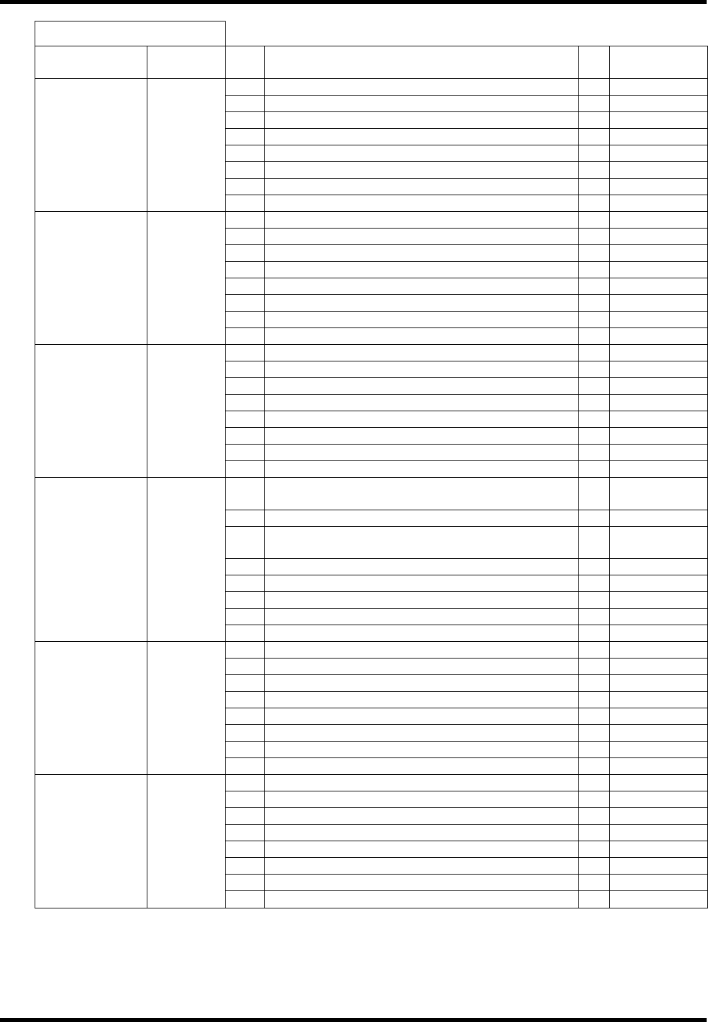
AV131
MAINTENANCE MANUAL
4.1 Control System Configuration
D79MEC-14-020-A0
4.1-20
I / O MAP OUTPUT
Board
connector
Address No. Name bit Note
1 04200: Right rail forward valve OUT 0
2 04201: Right rail reverse valve: OUT 1
3 04220: Right belt motor right turn: OUT 2
4 04221: Right belt motor reverse turn: OUT 3
5 00324: Safety stop support valve: OUT 4
6 5
7 6
#0_CN5 0020
8 7
9 0
10 1
11 Recognition light source ON 2
12 Recognition light source ON 3
13 Recognition light source ON 4
14 5
15 6
#0_CN7 0021
16 7
17 04205: PCB position right: OUT (OP) 0 Option
18 1
19 2
20 3
21 00316: PCB supply valve: OUT (OP) 4 Option
22 04216: PCB stopper 1 valve: OUT (OP) 5 Option
23 6
#0_CN9 0022
24 7
25
00306: ZR axis parts changing lamp output:
OUT
0
26 00321: ZR axis parts changing signal: OUT 1
27
00305: ZL axis parts changing lamp output:
OUT
2
28 00320: ZL axis parts changing signal: OUT 3
29 4
30 5
31 6
#0_CN6 0023
32 7
33 04202: Left rail forward valve 0
34 04203: Left rail reverse valve: OUT 1
35 04222: Left belt motor right turn: OUT 2
36 04223: Left belt motor reverse turn: OUT 3
37 04204: Positioner lever valve: OUT 4
38 5
39 6
#1_CN5 0060
40 7
41 04210: Inverter forward signal: OUT 0
42 04211: Inverter reverse signal: OUT 1
43 04212: Inverter speed command 1: OUT 2
44 04213: Inverter speed command 2: OUT 3
45 04214: Inverter abnormal reset: OUT 4
46 04215: Transfer brake release: OUT 5
47 6
#1_CN7 0061
48 7