Maintenance Manual.pdf - 第86页
AV131 MAINTENANCE MANUAL 4.1 Cont rol Sy ste m Confi guration D79MEC- 14-020-A0 4.1- 15 4.1. 6 I/O M ap I/O M A P INPU T Board conne ct or Address No . Name bi t Not e 1 04020: Ri ght ra il t rav ers e lim it : I N 0 2 0…
AV131
MAINTENANCE MANUAL
4.1 Control System Configuration
D79MEC-14-020-A0
4.1-14
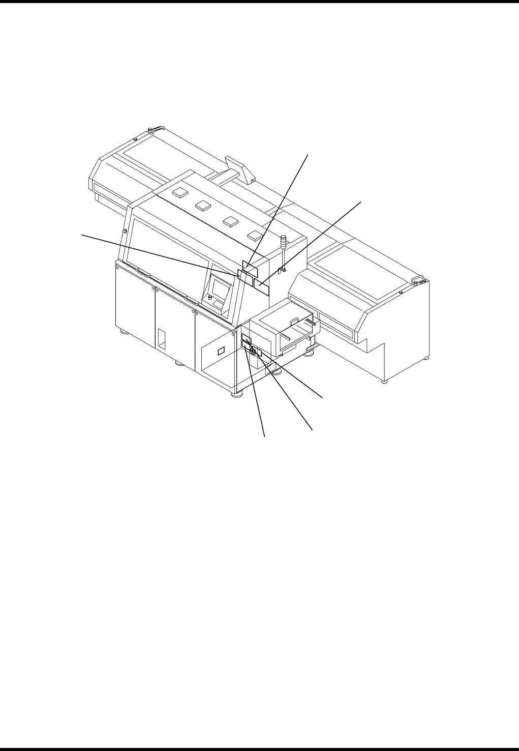
4.1.5 Ring I/O Load Board Arrangement
5.
6. (OPTION)
4.
3.
2.
1.
AV131
MAINTENANCE MANUAL
4.1 Control System Configuration
D79MEC-14-020-A0
4.1-15
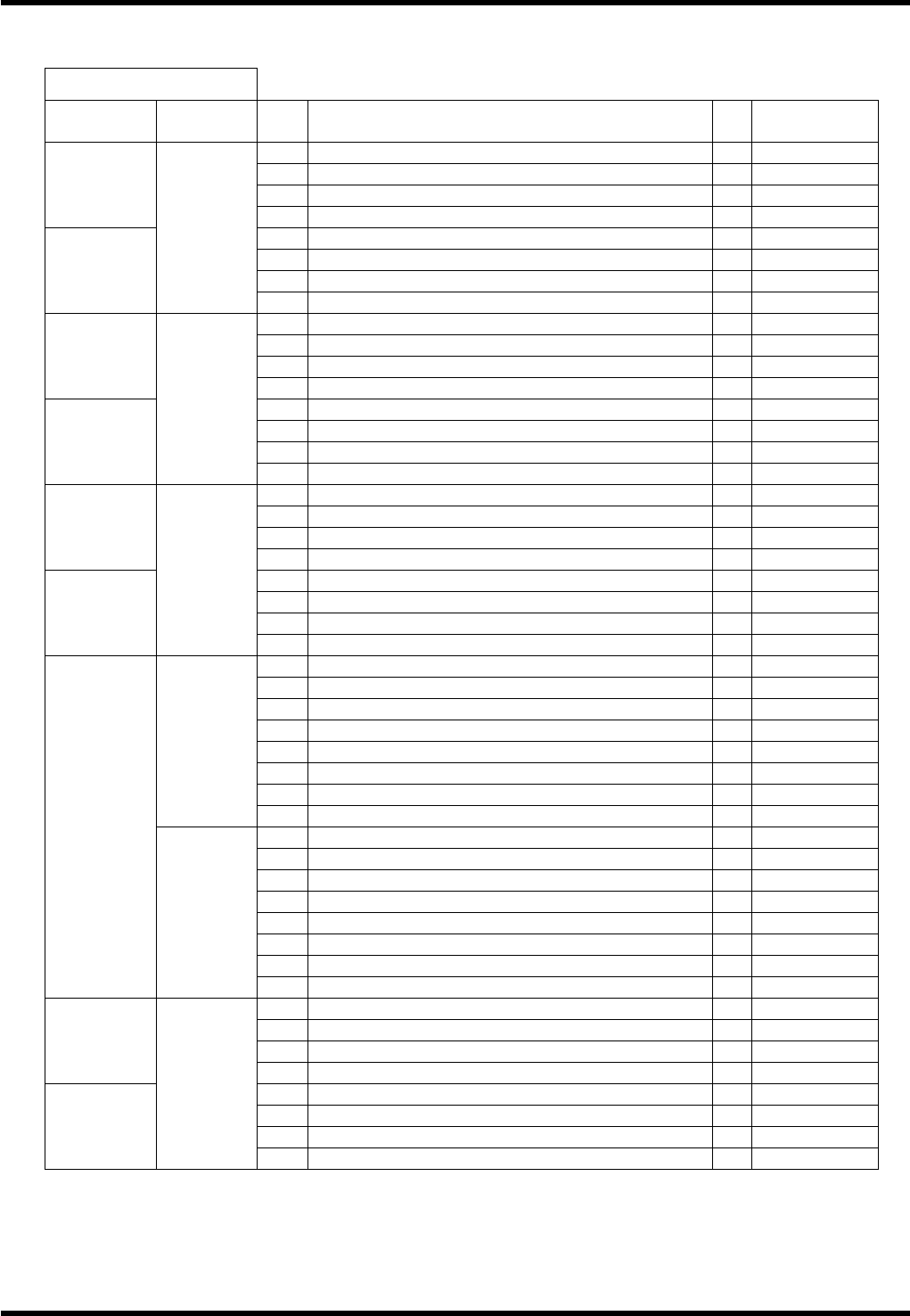
4.1.6 I/O Map
I/O MAP INPUT
Board
connector
Address No. Name bit Note
1 04020: Right rail traverse limit: IN 0
2 04021: Right rail return limit: IN 1
3 04022: PCB detection 1: IN 2
#0_CN16
4 04023: PCB detection 2: IN 3
5 04032: Carry arm return detection: IN 4
6 04033: Carry arm slow down detection: IN 5
7 04034: Carry arm traverse detection: IN 6
#0_CN15
0000
8 7
9 Main frame left side fan alarm: IN 0
10 Main frame controller fan alarm 1
11 Main frame right side fan alarm 2
#0_CN14
12 3
13 TABLE GAP DETECT (-S214) 4
14 ZR motor thermal 5
15 00116: ZR cassette gap detection: IN 6
#0_CN13
0001
16 7
17 WA AXIS ORG. 0
18 1
19 2
#0_CN12
20 3
21 04047: MLP input signal: IN (OP) 4 Option
22 00120: Air down: IN 5
23 6
#0_CN11
0002
24 7
25 04010: XY table inside PCB detection: IN 0
26 04013: Positioner error detection: IN 1
27 04016: XY table inside PCB detection 2: IN (OP) 2 Option
28 00056: 2 PCB transfer: IN (OP) 3 Option
29 04014: Positioner lever traverse limit: IN 4
30 04015: Positioner lever return limit: IN 5
31 6
0003
32 7
33 X AXIS+LIMIT 0
34 X AXIS ORG. 1
35 X AXIS-LIMIT 2
36 3
37 Y AXIS+LIMIT 4
38 Y AXIS ORG. 5
39 Y AXIS-LIMIT 6
#0_CN10
0004
40 7
41 Cover LEFT SIDE AT FRONT COVER (-S303) 0
42 1
43 04006: Push arm / push up traverse limit: IN 2
#1_CN16
44 04007: Push arm / push up return limit: IN 3
45 04000: Left rail traverse limit: IN 4
46 04001: Left rail return limit: IN 5
47 04002: PCB detection 3: IN 6
#1_CN15
0040
48 04003: PCB detection 4: IN 7
AV131
MAINTENANCE MANUAL
4.1 Control System Configuration
D79MEC-14-020-A0
4.1-16
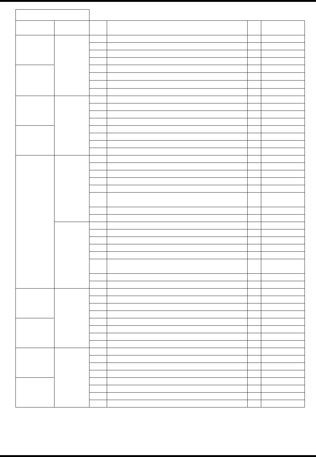
I / O MAP INPUT
Board
connector
Address No. Name bit Note
49 ZL motor thermal 0
50 00116: ZL cassette gap detection: IN 1
51 2
#1_CN14
52 3
53
θA AXIS+LIMIT (AV) / Aθ AXIS+LIMIT (RH)
4
54
θA AXIS ORG. (AV) / Aθ AXIS ORG. (RH)
5
55
θA AXIS-LIMIT (AV) / Aθ AXIS-LIMIT (RH)
6
#1_CN13
0041
56 7
57 00100: Insertion check 1: IN 0
58 00101: Insertion check 2: IN 1
59 2
#1_CN12
60 3
61 4
62 5
63 04030: Invertor run signal: IN 6
#1_CN11
0042
64 04031: Invertor abnormal signal: IN 7
65 00115: ZR change SW: IN 0
66 00136: ZR shunting SW check signal: IN 1
67 ZR AXIS +LIMIT 2
68 ZR AXIS ORG. 3
69 ZR AXIS -LIMIT 4
70
Cover RIGHT SIDE OF CENTER AT REAR
COVER
5
71 6
0043
72 7
73 00111: ZL change SW: IN 0
74 00135: ZR shunting SW check signal: IN 1
75 ZL AXIS +LIMIT 2
76 ZL AXIS ORG. 3
77 ZL AXIS -LIMIT 4
78
Cover LEFT SIDE OF CENTER AT REAR
COVER
5
79 6
#1_CN10
0043
80 7
81 00052: Parts detection 0
82 00053: Tape cutter damper valve: IN 1
83 00054: Feeder detection (52mm): IN 2
#2_CN16
84 3
85 00062: JW set traverse limit: IN 4
86 00063: JW set return limit: IN 5
87 6
#2_CN15
0080
88 7
89 00061: 26 mm shunting detection 0
90 1
91 2
#2_CN14
92 3
93 00066: H axis brake release: IN 4
94 00067: H axis brake SW: IN 5
95 WH AXIS ORG. 6
#2_CN13
0081
96 7