Maintenance Manual.pdf - 第76页
AV131 MAINTENANCE MANUAL 4.1 Cont rol Sy ste m Confi guration D79MEC- 14-020-A0 4.1- 5 MBDD T2210N01 (For X axis) M A DD T1205N01 (For WH, W A, U and V axes)
AV131
MAINTENANCE MANUAL
4.1 Control System Configuration
D79MEC-14-020-A0
4.1-4
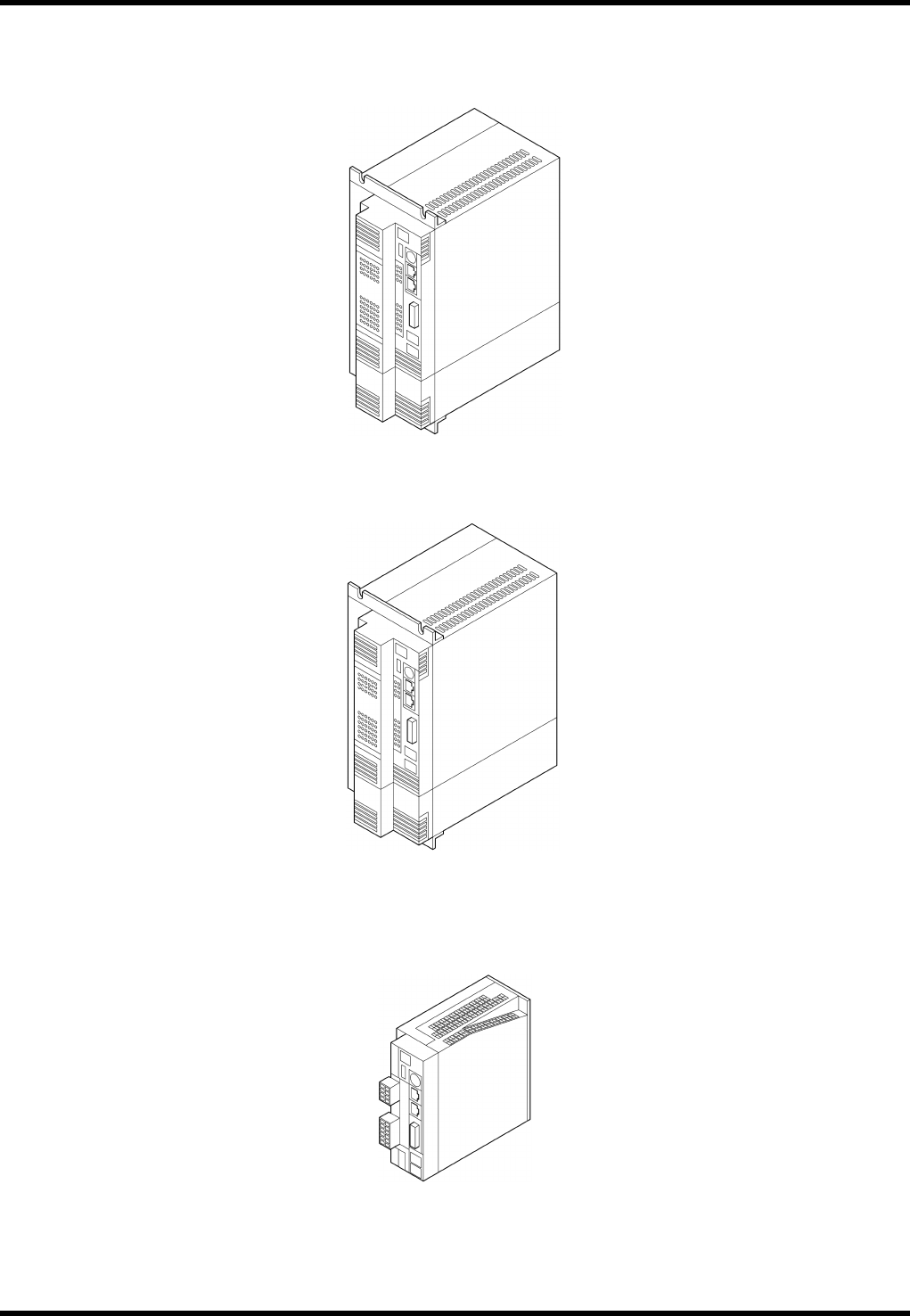
4.1.4 Driver
MFDDTA390N01 (For H axis)
MFDDTB3A2N01 (For θH, ZL (Exclusive for 120 inputs) and ZR axes)
MCDDT3520N01 (For Y, T and θA axes)
AV131
MAINTENANCE MANUAL
4.1 Control System Configuration
D79MEC-14-020-A0
4.1-5
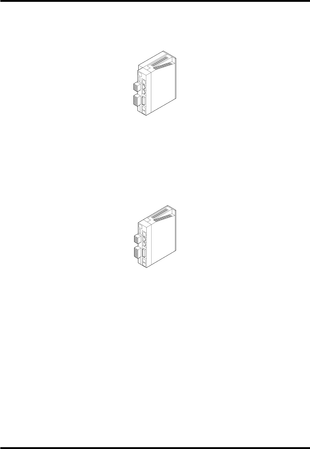
MBDDT2210N01 (For X axis)
MADDT1205N01 (For WH, WA, U and V axes)

AV131
MAINTENANCE MANUAL
4.1 Control System Configuration
D79MEC-14-020-A0
4.1-6
Warning Functions
This motor driver has a function to issue warnings before protective functions are activated, which allows the
user to check for possible abnormal condition such as overload.
When any of the following warnings has occurred, the warning code flashes slowly on the 7-segment LED
on the front panel.
Warning code
No.
Warning Details
16 Overload Load has exceeded 85% of the alarm level.
18 Regenerative overload Regenerative load has exceeded 85% of the alarm level.
40 Battery
The absolute encoder battery voltage has dropped to approx.
3.2V or below.
88 Locked fan Fan is stopped for more than 1 s.
89 External scale
External scale temperature is 65°C or higher, or signal
strength is insufficient (Adjustment (installation, etc.) is
required.). Available only during full-closed control.
If the overload or regenerative overload warning is detected, take the remedial action in the same way
as when the respective protective functions have occurred.
If the battery warning has occurred, replace the battery for the absolute encoder.
After replacing the battery, clear the alarm of the servo amplifier once to reset the battery warning.
Protective Functions (Detailed Description of Error Codes)
Function
Error
code No.
Cause Countermeasure
Insufficient
control
voltage
11
Voltage between P and N of the
control power converter dropped to
below the rated value.
1. Low power supply voltage.
Instantaneous power failure
occurred.
2. Insufficient power capacity:
Voltage dropped due to rush
current at power ON.
3. Faulty servo amplifier (circuit).
Measure the line voltage between the
control power input terminals ‘connectors
(L1C, L2C) and terminal blocks (r, t)’.
1. Increase the power voltage capacity.
Change the power supply.
2. Increase the power capacity.
3. Replace the servo amplifier.
Overvoltage 12
Voltage between P and N of the
converter exceeded the rated value.
1. The power voltage exceeded the
allowed input voltage range.
Sudden rise in the voltage by the
phase advance capacitor or UPS
(uninterruptible power supply).
2. Regenerative resistor
disconnected.
3. Regenerative energy cannot be
absorbed due to improper external
regenerative resistor.
4. Faulty servo amplifier (circuit).
Measure the line voltage of the main power
input terminal ‘connectors (L1, L2, L3)’.
1. Input the voltage properly. Remove the
phase advance capacitor.
2. Measure the resistance of the resistor
externally installed between the terminals
P and B of the servo amplifier using a
tester. If the value is ∞ (infinite), wire is
broken. Replace the external resistor.
3. Change to the specified regenerative
4. Replace the servo amplifier.