SIPLACE D4 规格说明书英文版.pdf - 第24页
24 Vision Sensor Technology PCB Position Recognition Description Different fiducial shapes prove to be optimal depend- ing on the condition of the surface. Particularly advis- able for bare copp er surfaces with little o…
23
Digital Vision System
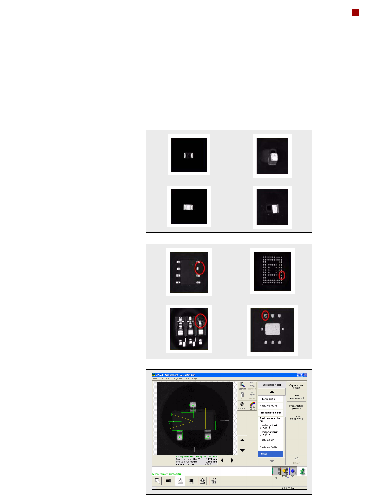
Checking the Component Quality
Flipped components Upright components
Poor component quality
Vision Teach menu at the station
SIPLACE vision algorithms
help with the detection of
• flipped components
•upright components
• poor component quality
The digital SIPLACE vision
system automatically saves
the last 500 images of com-
ponents that were identified
as "bad". SIPLACE users can
then easily demonstrate poor
component quality.
The benefits at a glance:
• Maximum placement
quality
• High first pass yield
• Reduced operating costs

24
Vision Sensor Technology
PCB Position Recognition
Description
Different fiducial shapes
prove to be optimal depend-
ing on the condition of the
surface. Particularly advis-
able for bare copper surfaces
with little oxidation is the
single cross. Maximum accur-
acy is achieved due to the
high information content.
Rectangle, square and circle
are less "informative" but
save space and can even be
used when oxidation is at an
advanced stage. Advisable
for tinned structures are
circle or square because in
this case the ratio of the fidu-
cial dimensions to the presol-
der thickness is particularly
favorable.
Fiducial criteria
Locate 2 fiducials
Locate 3 fiducials
X-/Y-position, rotation angle, mean PCB distortion
in addition: shear, distortion in X- and Y-direction separately
Fiducial shapes Synthetic fiducials: circle, cross, square, rectangle, rhombus,
circular, square, and rectangular contours, double cross, any
pattern
Fiducial surface:
copper
tin
Without oxidation and solder resist
Fiducial warp 1/10 of structure width, both with good
contrast to environment
Dimensions of synthetic fiducials
min. X/Y size for circle and rectangle: 0.25 mm
min. X/Y size for annulus and rectangle: 0.3 mm
min. X/Y size for cross: 0.3 mm
min. X/Y size for double-cross: 0.5 mm
min. X/Y size for lozenge: 0.35 mm
min. frame width for annulus and rectangle: 0.1 mm
min. bar width / bar distance for cross, double-cross: 0.1 mm
max. X/Y size for fiducial shapes: 3 mm
max. bar width for cross / double-cross: 1.5 mm
min. tolerances, general: 2% of nominal dimension
max. tolerances, general: 20% of nominal dimension
Dimensions of patterns
min. size
max. size
0.5 mm
3 mm
Fiducial environment Clearance around reference fiducial not necessary if there is
no similar fiducial structure in the search area

25
Vision Sensor Technology
PCB Position Recognition
Bad Board Position Recognition
Ink spot criteria
Methods • Synthetic fiducial recognition method
• Mean grayscale value
• Histogram method
•Template matching
Shapes and sizes of fiducials/structures for
synthetic fiducials
other methods
For dimensions of synthetic fiducials, see page 24
min. 0.3 mm
max. 5 mm
Masking material good coverage
Recognition time depends on the method: 20 ms - 200ms
Description
In the cluster technology
each subpanel is assigned an
ink spot. If this is present
during the measurement via
the PCB vision module, the
corresponding subpanel is
populated.
With this function it is pos-
sible to eliminate costs due to
unnecessary population of
faulty subpanels.
Technical data for PCB position recognition
PCB fiducials
Local fiducials
Library memory for recognition
of bad panels
up to 3 (subpanels and multiple panels)
up to 6 for the Long board option (Optional PCB fiducials
are output by the optimization.)
up to 2 per PCB (may be of different type)
up to 255 fiducial types per subpanel
Image analysis Edge detection method (Singular feature) based on gray-
scale values
Lighting method Front lighting
Fiducial recognition time 0.1 s
Field of vision 5.78 x 5.78 mm