00197295-01_UM_D4i_SR605_EN.pdf - 第66页
2 Operational safety User manual SIPLACE D4i 2.6 Safety equipment From software version SR.605.03 SP2 10/2012 EN edition 66 Push-button for raising the CO tables (item 2 in Fig. 2.6 - 6 ) 2 Use the push-butto ns to raise…

User manual SIPLACE D4i 2 Operational safety
From software version SR.605.03 SP2 10/2012 EN edition 2.6 Safety equipment
65
Component counter (item 4 in Fig. 2.6 - 3) 2
This displays the number of inserted components.
EMERGENCY STOP button with positive latching (item 5 in Fig. 2.6 - 3 and item 1 in Fig. 2.6 - 4)2
The EMERGENCY STOP button is red and latches in the ON position when pressed. When you
press the EMERGENCY-STOP button the switching contact of the safety circuit opens and the
protective contactor combination (PCC K1) trips. The link voltage (200 V) for the gantry axes and
the link voltage (150 V) for the star axes is switched off. The servo amplifiers for the DP and Z
axes are still supplied with 40 VDC. The signaling contact of the EMERGENCY-STOP button
closes and the message "EMERGENCY-STOP pressed" appears on the screen. The following
modules will be activated:
– PCB conveyor
– PCB clamping
– Width adjustment
– Laser light barrier and
– Used tape cutter
PLEASE NOTE
Placement is interrupted and can then either be continued or canceled once the machine is work-
ing correctly again. 2
Protective cover switches 1, 2, 3 and 4 (item 1, 2, 3 and 4 in Fig. 2.6 - 5) and protective switch
for the cover flaps on the PCB conveyor input and output side (items 5 and 6 in Fig. 2.6 - 5
) 2
These switches check whether the protective covers and the cover flaps are closed. When they
are closed, the EMERGENCY STOP contact is closed and the signaling contact is open. If one of
the covers or the cover flaps is opened, the EMERGENCY STOP contact opens and the signaling
contact closes. Some components are deactivated or remain active (see Fig. 2.6 - 8
, page 69).
Sockets for connecting the CO trolleys (item 1 in Fig. 2.6 - 6) 2
These sockets are used to supply the necessary voltages and compressed air to the CO trolleys.
The terminals for the safety and signaling circuits are also integrated into these sockets. This pre-
vents the machine being started up before the component trolleys. If the component trolley is not
connected, the protective contactor combination trips and deactivates all the modules.

2 Operational safety User manual SIPLACE D4i
2.6 Safety equipment From software version SR.605.03 SP2 10/2012 EN edition
66
Push-button for raising the CO tables (item 2 in Fig. 2.6 - 6) 2
Use the push-buttons to raise and lower the component trolley table bed. To use this push-button,
and thus the drives for the component table you must first move the placement head out of the
range of the component table and open the flap over the button. After changing the component
table, you must first close the flap over the button once again.
– If the flap is closed, the EMERGENCY STOP circuit contact will close and the signaling con-
tact will open. The machine is then ready for use.
– If the flap is open, the EMERGENCY STOP circuit is interrupted and the signaling contact
closes. An error message will appear on the screen prompting you to close the flap. The ma-
chine can then be restarted using the start button.
User manual SIPLACE D4i 2 Operational safety
From software version SR.605.03 SP2 10/2012 EN edition 2.6 Safety equipment
67
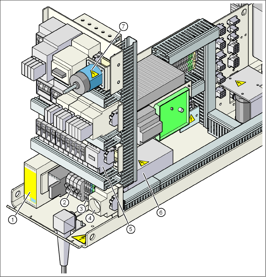
2.6.3 Position of protective contactor combination and service socket
2
Fig. 2.6 - 7 Position of protective contactor combination and service socket
(1) Protective contactor combination K1
(2) Fuses FU, FV, FW, FBU
(3) Infeed terminals X100
(4) BU1 service socket
(5) Discharge reactor Z2
(6) Line filter Z1
(7) Main power switch S1