00197295-01_UM_D4i_SR605_EN.pdf - 第71页
User manual SIPLACE D4i 2 Operational safety From software version SR.605.03 SP2 10/2012 EN edition 2.6 Safety equipment 71 2 Fig. 2.6 - 9 Emergency stop loops S tart button pressed No No Ye s No No Ye s Ye s No Ye s 2 A…
2 Operational safety User manual SIPLACE D4i
2.6 Safety equipment From software version SR.605.03 SP2 10/2012 EN edition
70
2.6.4.2 Structure of the signaling circuit
The six signaling contacts for the covers are connected in parallel and form the "cover signal" cir-
cuit. If one or more covers are opened, the contacts close, and the 24 V signal reaches the CAN
bus and signals that one of the covers is open.
The two signaling contacts for the EMERGENCY STOP buttons are connected in parallel and form
the "EMERGENCY STOP button signal circuit". When an EMERGENCY STOP button is pressed,
a 24 V signal is sent to the CAN bus and signals that one of the EMERGENCY STOP buttons has
been pressed.
The four signaling contacts for the push-button flaps are connected in parallel. They form the "Flap
signal" circuit. If one or more flaps is raised, a 24 V signal is applied to the CAN bus and signals
that one of the cover flaps is not closed.
The four signaling contacts for the CO trolleys are connected in series and form the "M-COTable"
signal loop. If a CO trolley is missing, a 0 V signal is sent to the CAN bus. If all trolleys are con-
nected, the signal is approximately 16 V.
2.6.4.3 Description of the functions of the EMERGENCY STOP loop
The following conditions must be fulfilled before the machine can be started or operated:
– All four component trolleys must be docked in and connected.
– All protective covers must be closed.
– Both cover flaps over the PCB conveyor must be closed.
– Both EMERGENCY STOP buttons must be released.
– All four flaps over the pushbuttons for raising the CO table must be closed.
– The minimum operating pressure must have been reached.
– The "software enable" signal must be active. This ensures that the EMERGENCY STOP loop
is closed.
– The power supply must be sending 24 V to the start buttons and the protective contactor com-
bination.
– If one of the start buttons is now pressed, the protective contactor combination PCC will
switch and activate the following components:
– 200 V link voltage for the servo amplifiers for the gantry axes
– 150 V link voltage for the star axes
– The axis unit will receive a "Servo Enable" signal for the servo amplifier.
– 34 V operating voltage is switched to the CO trolleys.
– 24 V operating voltage is switched to the used tape cutters.
– The PCB conveyor control receives the enable signal for the PCB clamping, the PCB stop-
per and the lifting table control.
The machine is then ready for use.
User manual SIPLACE D4i 2 Operational safety
From software version SR.605.03 SP2 10/2012 EN edition 2.6 Safety equipment
71
2
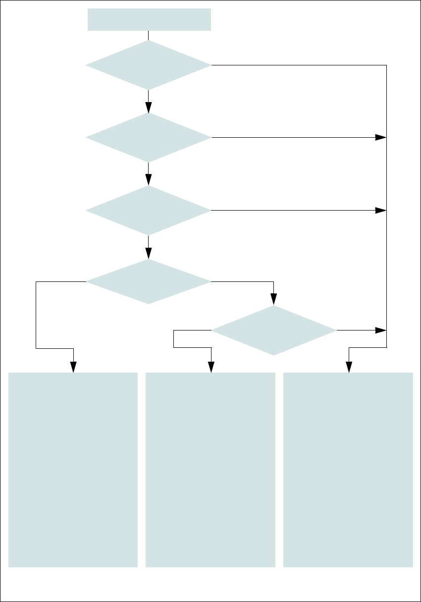
Fig. 2.6 - 9 Emergency stop loops
Start button pressed
No
No
Yes
No
No
Yes
Yes
No
Yes
2
Active
PCC*) No
SZ4 **) Yes
Voltage
Y axis 0 V
X axis 0 V
Star axis 0 V
DP axis 40 VDC
Z axis 40 VDC
Active
PCB conveyor Yes
Lifting table No
PCB clamp No
Width adjustment No
Laser light barrier No
Used tape cutter No
2
Active
PCC*) No
SZ4 **) No
Voltage
Y axis 0 V
X axis 0 V
Star axis 0 V
DP axis 40 VDC
Z axis 40 VDC
Active
PCB conveyor No
Lifting table No
PCB clamp No
Width adjustment No
Laser light barrier No
Used tape cutter No
*) PCC protective contactor combination K1
**) SZ4 contactor
Yes
Compressed
air min. 0.55 MPa
(5.5 bar)?
EMERGENCY STOP
button pressed?
Protective cover open ?
Component trolley
EMERGENCY STOP circuit
interrupted?
Barrier
activated on the user
interface?
2
Active
PCC*) Yes
SZ4 **) Yes
Voltage
Y axis 200 VDC
X axis 200 VDC
Star axis 150 VDC
DP axis 40 VDC
Z axis 40 VDC
Active
PCB conveyor Yes
Lifting table Yes
PCB clamp Yes
Width adjustment Yes
Laser light barrier Yes
Used tape cutter Yes
2 Operational safety User manual SIPLACE D4i
2.6 Safety equipment From software version SR.605.03 SP2 10/2012 EN edition
72
2.6.5 Guard on the component trolley locations
WARNING 2
All locations must be equipped with feeder modules in order to guarantee operational reliability. If
there are not enough feeder modules available, unassigned locations should be fitted with a
hand guard (dummy feeder module).
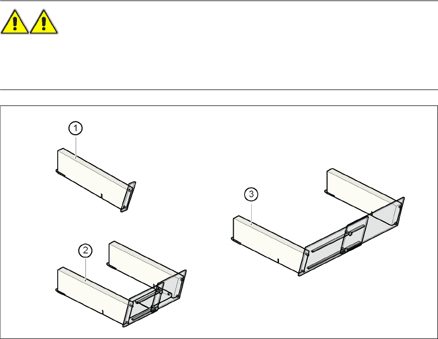
Fig. 2.6 - 10 Hand guard for component trolleys
2
(1) Hand guard for 1 location item no. 00116961-01
(2) Hand guard for 6 to 10 locations item no. 00116962-01
(3) Hand guard for 11 to 20 locations item no. 00116963-01