00197295-01_UM_D4i_SR605_EN.pdf - 第67页
User manual SIPLACE D4i 2 Operational safety From software version SR.605.03 SP2 10/2012 EN edition 2.6 Safety equipment 67 2.6.3 Position of protective cont actor combination and service socket 2 Fig. 2.6 - 7 Position o…

2 Operational safety User manual SIPLACE D4i
2.6 Safety equipment From software version SR.605.03 SP2 10/2012 EN edition
66
Push-button for raising the CO tables (item 2 in Fig. 2.6 - 6) 2
Use the push-buttons to raise and lower the component trolley table bed. To use this push-button,
and thus the drives for the component table you must first move the placement head out of the
range of the component table and open the flap over the button. After changing the component
table, you must first close the flap over the button once again.
– If the flap is closed, the EMERGENCY STOP circuit contact will close and the signaling con-
tact will open. The machine is then ready for use.
– If the flap is open, the EMERGENCY STOP circuit is interrupted and the signaling contact
closes. An error message will appear on the screen prompting you to close the flap. The ma-
chine can then be restarted using the start button.
User manual SIPLACE D4i 2 Operational safety
From software version SR.605.03 SP2 10/2012 EN edition 2.6 Safety equipment
67
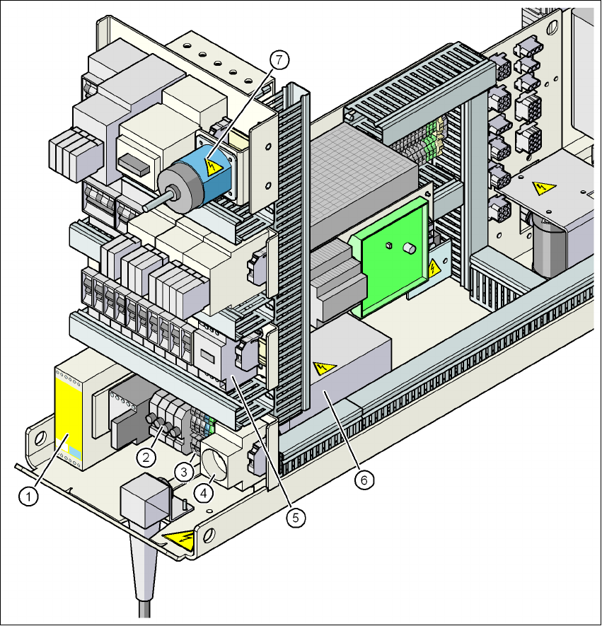
2.6.3 Position of protective contactor combination and service socket
2
Fig. 2.6 - 7 Position of protective contactor combination and service socket
(1) Protective contactor combination K1
(2) Fuses FU, FV, FW, FBU
(3) Infeed terminals X100
(4) BU1 service socket
(5) Discharge reactor Z2
(6) Line filter Z1
(7) Main power switch S1
2 Operational safety User manual SIPLACE D4i
2.6 Safety equipment From software version SR.605.03 SP2 10/2012 EN edition
68
Protective contactor combination 3TK2825 (item 1 in Fig. 2.6 - 7) 2
The protective contactor combination is contained in the power supply unit. It is used to monitor
the EMERGENCY STOP circuits and safety equipment.
There are three conditions that must be fulfilled in order to activate the protective contactor com-
bination:
– The "software enable" signal must have been sent.
– The EMERGENCY STOP loop must be closed.
– The start button must have been pressed.
On the front panel of the protective contactor combination, there are three green operating display
LEDs (see Fig. 2.6 - 8
, page 69):
– The "Power" LED indicates that voltage is present.
– The "Channel 1" and "Channel 2" LEDs light up if the start button was pressed, the EMER-
GENCY STOP loop is closed and the signaling circuit is not signaling a fault status.
Service socket (item 4 in Fig. 2.6 - 7) 2
The service socket is contained in the power supply unit and is protected by the cover. It can only
be used if the machine is connected to the main power supply via a 5-wire connection (U, V, W,
N, and PE). If a 4-wire connection is used, e.g. without N, the socket cannot be used.
WARNING 2
Always follow the safety instructions concerning potentially lethal voltages - even when the
machine is switched off (see Section 2.6.2.4 from page 64).