00197295-01_UM_D4i_SR605_EN.pdf - 第96页
3 Technical data for the machine User manual SIPLACE D4i 3.5 Placement head From software version SR.605.03 SP2 10/2012 EN edition 96 3.5 Placement head 3.5.1 12-nozzle Collect&Place head Item no. 001 19876-xx, 12-no…
User manual SIPLACE D4i 3 Technical data for the machine
From software version SR.605.03 SP2 10/2012 EN edition 3.4 Overview of the modules
95
3.4 Overview of the modules
3
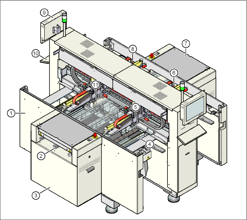
Fig. 3.4 - 1 Overview of the modules
(1) Machine frame
(2) PCB conveyor (flexible dual conveyor)
(3) Extension kit on the PCB input side
(4) Tape cutter, used tape channel (4x)
(5) Gantry 1
(6) Gantry 2
(7) Extension kit on the PCB output side
(8) Gantry 3
(9) Monitor (2x)
(10) Keyboard (2x)
(11) Gantry 4
3 Technical data for the machine User manual SIPLACE D4i
3.5 Placement head From software version SR.605.03 SP2 10/2012 EN edition
96
3.5 Placement head
3.5.1 12-nozzle Collect&Place head
Item no. 00119876-xx, 12-nozzle C&P head D4i/D2i/D1i
3
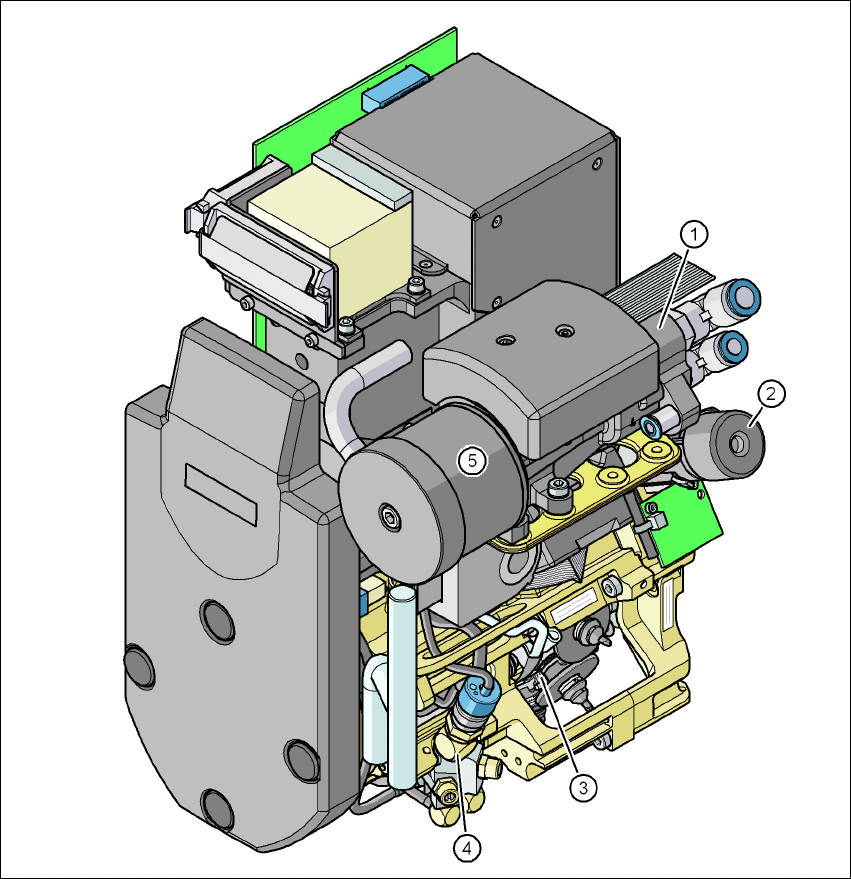
Fig. 3.5 - 1 12-nozzle Collect&Place head - Function groups, part 1
3
(1) Vacuum generator
(2) Turning station, DP axis
(3) Star with 12 sleeves, star axis
(4) Forced air valve
(5) Silencer
User manual SIPLACE D4i 3 Technical data for the machine
From software version SR.605.03 SP2 10/2012 EN edition 3.5 Placement head
97
3
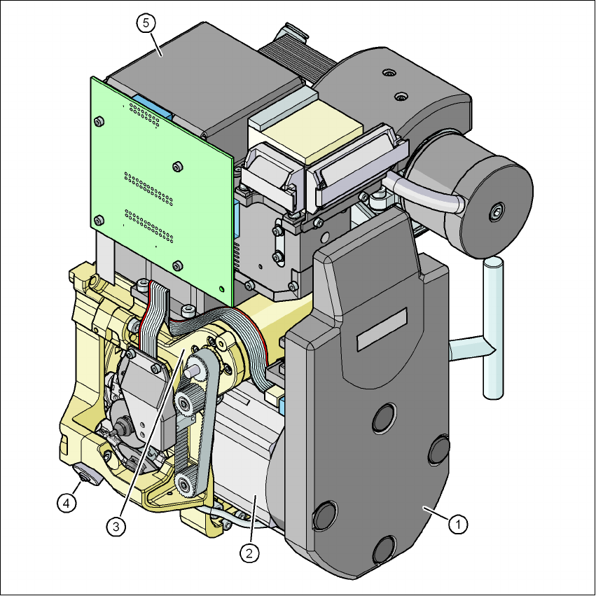
Fig. 3.5 - 2 12-nozzle Collect&Place head - Function groups, part 2
3
(1) Intermediate distributor board (beneath the cover)
(2) Star drive - DR motor
(3) Z axis motor
(4) Valve adjustment drive
(5) C&P component camera
3.5.1.1 Description
The 12-nozzle Collect&Place head works on the Collect&Place principle. This means that, within
each cycle, twelve components are picked up by the placement head, are optically centered on
the way to the placement position and are rotated into the required placement angle. They are