Service Manual SIPLACE SmartFeeder.pdf - 第81页
6 Repairs to SmartFeeder 4 mm X / Xi 6.16 Control board Service Manual SIPLACE SmartFeeder 4 - 8 mm X / Xi SIPLACE SmartFeeder 2 x 8 mm X / Xi 11/2020 81 6.16 Control board CAUTION Electrostatic charge When removing and …
6 Repairs to SmartFeeder 4 mm X / Xi
6.15 Handle with control panel
80 Service Manual SIPLACE SmartFeeder 4 - 8 mm X / Xi SIPLACE SmartFeeder 2 x 8 mm X / Xi 11/2020
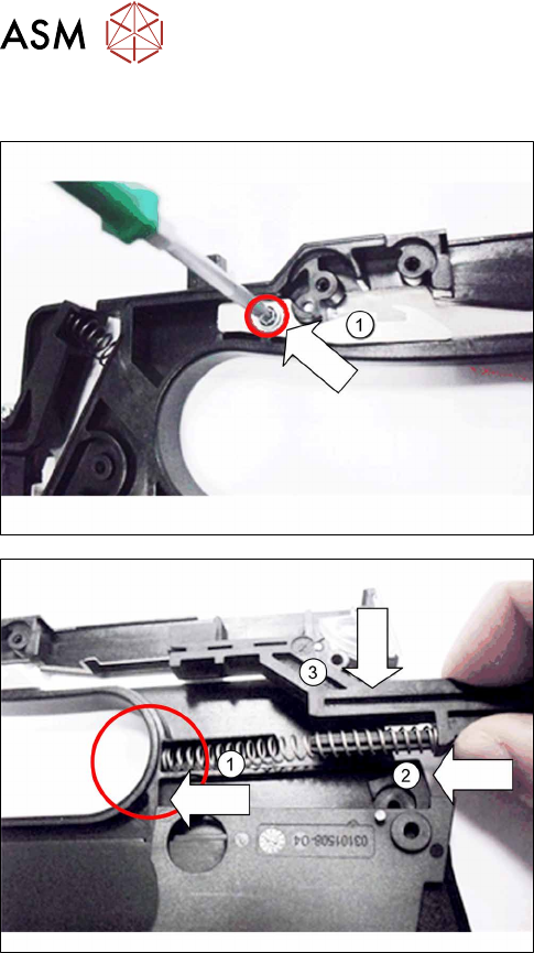
6.15.3.2 Fitting individual parts to the handle
► Hold the spring hook as shown(1) by the handle,
so that you can look through the opening and see
the hole for the screw.
► Screw the spring hook to the handle. Use a size
T8 TORX screwdriver with 0.6 Nm for this.
► Push one end of the pressure spring in the
handle, as shown.(1)
► Insert the slide into the other end of the pressure
spring.(2)
► Press the slide into the pressure spring and insert
it from above, into the handle.(3)
At this point, the cover on the foil stuffing unit will be accessible and can be replaced if necessary,
before you fit the control panel.
► Fasten the control panel (see 6.15.2.2 "Fitting the Control Panel and Board" [}77]).
► Fasten the left side cover (see 6.3.2 "Fitting the Left Side Cover" [}30]).
6 Repairs to SmartFeeder 4 mm X / Xi
6.16 Control board
Service Manual SIPLACE SmartFeeder 4 - 8 mm X / Xi SIPLACE SmartFeeder 2 x 8 mm X / Xi 11/2020 81
6.16 Control board
CAUTION
Electrostatic charge
When removing and fitting the control board, observe the currently applicable ESD
guidelines.
Required spare part
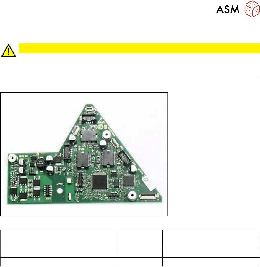
Fig.24: Example control board X8Smart V2
Feeder module Item no. Designation
SmartFeeder 4mmX (V2) 03101127-xx Control board X8Smart V2
SmartFeeder 4mmX (V3) 03124276-xx Control board X8Smart V3
SmartFeeder 4 mm Xi 03160015-xx Control board X8Smart Xi
Tools required
●
Phillips screwdriver 0.9Nm
●
TORX screwdriver 0.6Nm and 0.2 Nm, size T8
6 Repairs to SmartFeeder 4 mm X / Xi
6.16 Control board
82 Service Manual SIPLACE SmartFeeder 4 - 8 mm X / Xi SIPLACE SmartFeeder 2 x 8 mm X / Xi 11/2020
6.16.1 Removing the control board
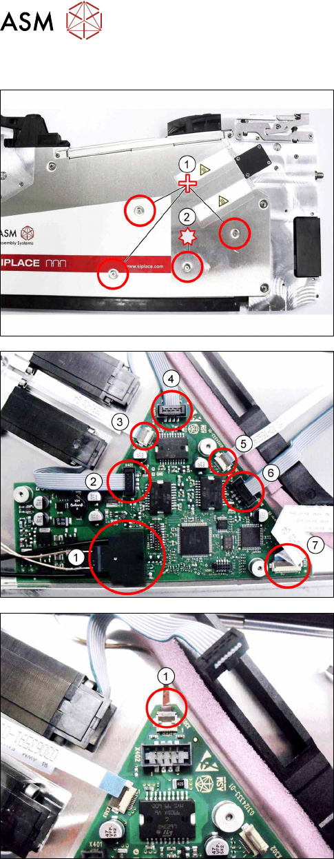
► Carefully place the feeder module with the left
side down on a stable, level and clean surface.
► Remove the three Phillips screws marked in the
picture(1)
, which fasten the control board to the
right side cover.
► Carefully remove the TORX screw shown in the
diagram(2)
, which fastens the EDIF connector to
the control board.
Use a size 8 TORX screwdriver for this.
► Carefully place the feeder module with the right
side down on a stable, level and clean surface.
► Remove the left side cover (see section 6.3.1
"Removing the Left Side Cover" [}30]).
► Remove the EDIF connector(1).
► Loosen the 6 connections shown in the dia-
gram(2 – 7)
.
► If there is a splice sensor fitted in the feeder mod-
ule, open the connection to the splice sensor
cable.(1)
► Remove the control board.