WAAAF_ES_IA.pdf - 第3页
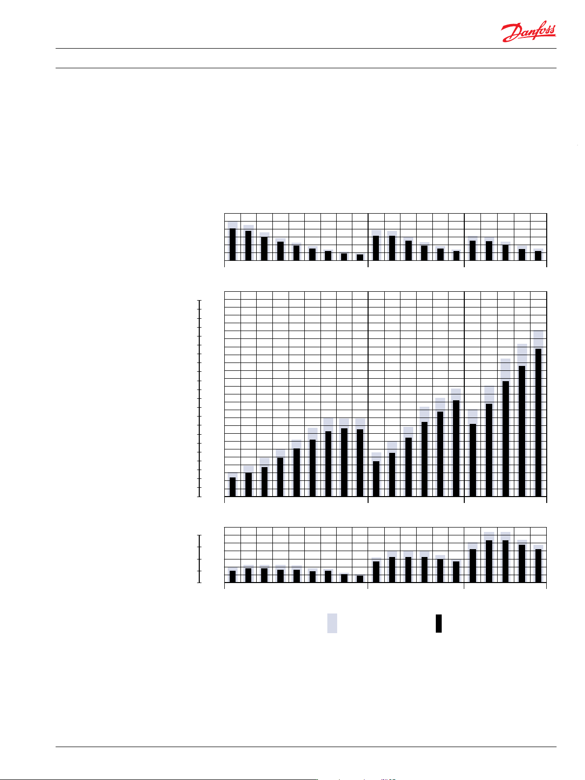
• OMV Function diagrams on page 81 The function diagrams are based on actual tests on a representative number of motors from our production. The diagrams apply to a return pressure between 5 and 10 bar [75 and 150 psi] w…
Speed, torque and output
80 100 125 160 200 250 315 400 500 160 200 250 315 400 500 315 400 500 630 800
80 100 125 160 200 250 315 400 500 160 200 250 315 400 500 315 400 500 630 800
80 100 125 160 200 250 315 400 500 160 200 250 315 400 500 315 400 500 630 800
800
600
400
200
22000
20000
18000
16000
14000
12000
10000
8000
6000
4000
2000
2400
2200
2000
1800
1600
1400
1200
1000
800
600
400
200
80
60
40
20
60
50
40
30
20
10
OMS OMT OMV
151-1407.11
hp kW
lbf•in
min
-1
(rpm)
Nm
Max. speed
Max. Torque
Max. output
Intermittend values Continuous values
The bar diagrams above are useful for a quick selection of relevant motor size for the application. The
final motor size can be determined by using the function diagram for each motor size.
•
OMS Function diagrams on page 18
•
OMT Function diagrams on page 54
Technical Information
OMS, OMT and OMV Orbital Motors
OMS, OMT and OMV
520L0407 • Rev 0601 • February 2016 7

•
OMV Function diagrams on page 81
The function diagrams are based on actual tests on a representative number of motors from our
production. The diagrams apply to a return pressure between 5 and 10 bar [75 and 150 psi] when using
mineral based hydraulic oil with a viscosity of 35 mm²/s [165 SUS] and a temperature of 50°C [120°F]. For
further explanation concerning how to read and use the function diagrams, please consult the paragraph
"Selection of motor size" in the technical information "General Orbital motors" 520L0232.
Technical Information OMS, OMT and OMV Orbital Motors
OMS, OMT and OMV
8 520L0407 • Rev 0601 • February 2016
Versions
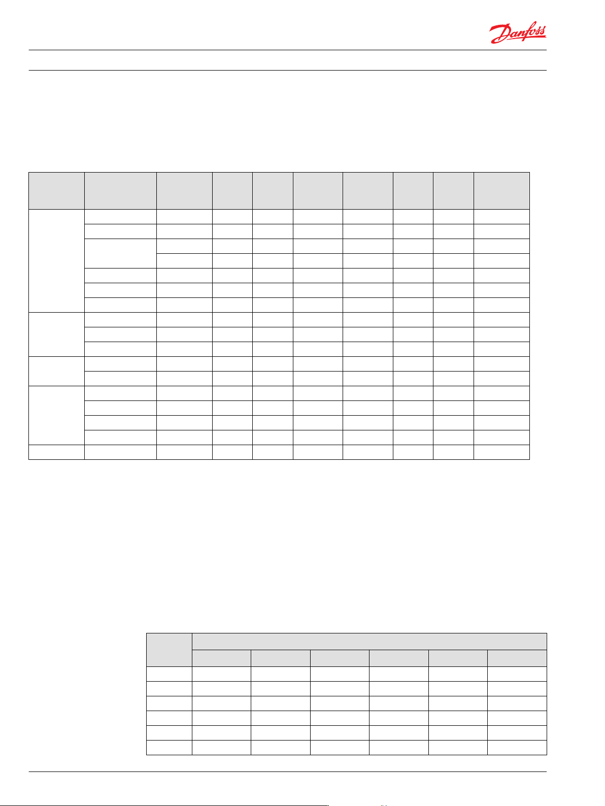
OMT versions
Mounting
flange
Shaft Port size Europea
n version
US
version
Drain
connection
Check valve Low
pressure
release
High
pressure
release
Main type
designation
Standard
flange
Cyl. 40 mm G 3/4 X Yes Yes OMT
Cyl. 1.5 in 1 1/16-12 UN X Yes Yes OMT
Splined 1.5 in G 3/4 X Yes Yes OMT
1 1/16-12 UN X Yes Yes OMT
Tapered 45 mm G 3/4 X Yes Yes OMT
Tapered 1.75 in 1 1/16-12 UN X Yes Yes OMT
P.t.o. G 3/4 X Yes Yes OMT
Wheel Cyl. 40 mm G 3/4 X Yes Yes OMTW
Tapered 45 mm G 3/4 X Yes Yes OMTW
Tapered 1.75 in 1 1/16-12 UN X Yes Yes OMTW
Brake-wheel Wheel bolt flange G 3/4 X Yes No X OMT FX
Thread hole flange G 3/4 X Yes No X OMT FX
Brake-
standard
Cyl. 40 mm G 3/4 X Yes No X OMT FL
Splined 1.5 in G 3/4 X Yes No X OMT FL
Cyl. 40 mm G 3/4 X Yes No X OMT FH
Splined 1.5 in G 3/4 X Yes No X OMT FH
Short No output shaft G 3/4 X Yes Yes OMTS
Features
Features available (options):
•
Speed sensor
•
Motor with tacho connection
•
Viton shaft seal
•
Painted
•
Ultra short
Code numbers
OMT code numbers
Code
Numbers
Displacement [cm
3
]
160 200 250 315 400 500
151B 3000 3001 3002 3003 3004 3005
151B 2050 2051 2052 2053 2054 2055
151B 3006 3007 3008 3009 3010 3011
151B 2056 2057 2058 2059 2060 2061
151B 3012 3013 3014 3015 3016 3017
151B 2062 2063 2064 2065 2066 2067
Technical Information OMS, OMT and OMV Orbital Motors
OMT
46 520L0407 • Rev 0601 • February 2016