WAAAF_ES_IA.pdf - 第9页
Direction of shaft rotation B B A A 151-1050.10 Permissible shaft loads for OMT Mounting flange: Standard Shaft: All shaft types 151-1967.10 -60 -40 -20 0 20 40 60 80 100 120 140 mm -2 -1.5 -1 -0.5 0 0.5 1 1.5 2 2.5 3 3.…
Brake motors
Type Maximum presssure in
drain line
3)
Holding torque
4)
Brake-release pressure
3)
Maximum pressure in
brake line
OMT FX, OMT FL 5 bar
[70 psi]
1200 Nm
[10620 lbf·in]
12 bar
[170 psi]
30 bar
[440 psi]
OMT FH 5 bar
[70 psi]
1200 Nm
[10620 lbf·in]
30 bar
[440 psi]
280 bar
[4060 psi]
1) Intermittent operation: the permissible values may occur for maximum 10% of every minute.
2) Peak load: The permissible values may occur for maximum 1% of every minute.
3) Brake motors must always have a drain line. The brake-release pressure is the difference between the
pressure in the brake line and the pressure in the drain line.
4) For the supply of motors with holding torques higher than those stated, please contact the Danfoss
sales organization.
For maximum permissible combination of flow and pressure, see function diagram for actual motor.
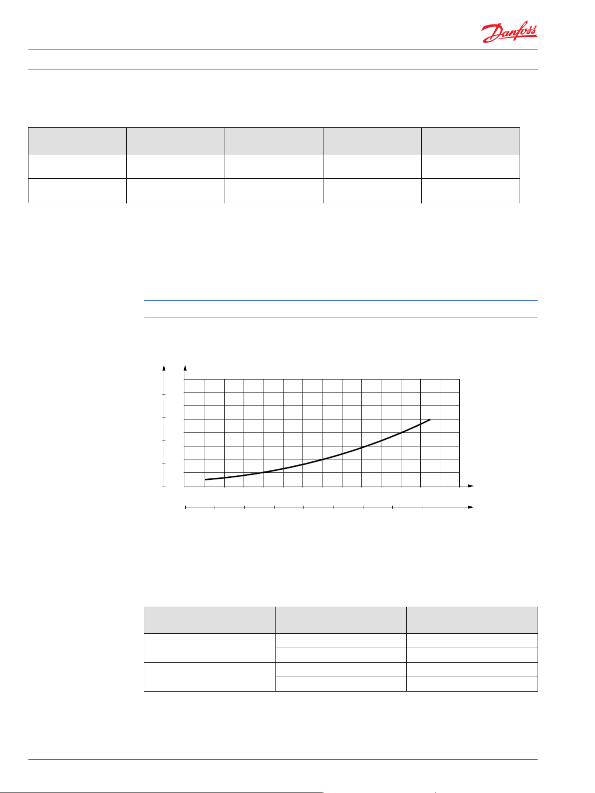
Pressure drop in motor
151-1409.10
0 20 40 60 80 100 120 140 l/min
0 4 8 12 16 20 24 28 32 36 US gal/min
200
150
100
50
0
16
14
12
10
8
6
4
2
0
psi bar
∆ p ∆ p
Q
Q
The curve applies to an unloaded motor shaft and an oil viscosity of 35 mm
2
/s [165 SUS]
Oil flow in drain line
Maximum oil flow in the drain line at a return pressure less than 5-10 bar [75-150 psi]
Pressure drop
bar [psi]
Viscosity
mm
2
/s [SUS]
Oil flow in drain line
l/min [US gal/min]
140
[2030]
20 [100] 2.5 [0.66]
35 [165] 1.5 [0.40]
210
[3050]
20 [100] 5.0 [1.32]
35 [165] 3.0 [0.79]
Technical Information OMS, OMT and OMV Orbital Motors
OMT
50 520L0407 • Rev 0601 • February 2016
Direction of shaft rotation
B BA A
151-1050.10
Permissible shaft loads for OMT
Mounting flange:
Standard
Shaft:
All shaft types
151-1967.10
-60 -40 -20 0 20 40 60 80 100 120 140 mm
-2 -1.5 -1 -0.5 0 0.5 1 1.5 2 2.5 3 3.5 4 4.5 5 5.5 in
14000
12000
10000
8000
6000
4000
2000
0
60000
50000
40000
30000
20000
10000
0
lbf N
P
rad.
P
rad.
P
max.
0
+-
=10000 N
=2248 lbf
Mounting flange:
Wheel
Shaft:
All shaft types
Technical Information
OMS, OMT and OMV Orbital Motors
OMT
520L0407 • Rev 0601 • February 2016 51
151-1970.10
0 20 40 60 80 100 120 140 160 mm
0 1 2 3 4 5 6 in
14000
12000
10000
8000
6000
4000
2000
0
60000
50000
40000
30000
20000
10000
0
lbf N
P
rad.
P
rad.
P
max.
0
+-
=10000 N
=2248 lbf
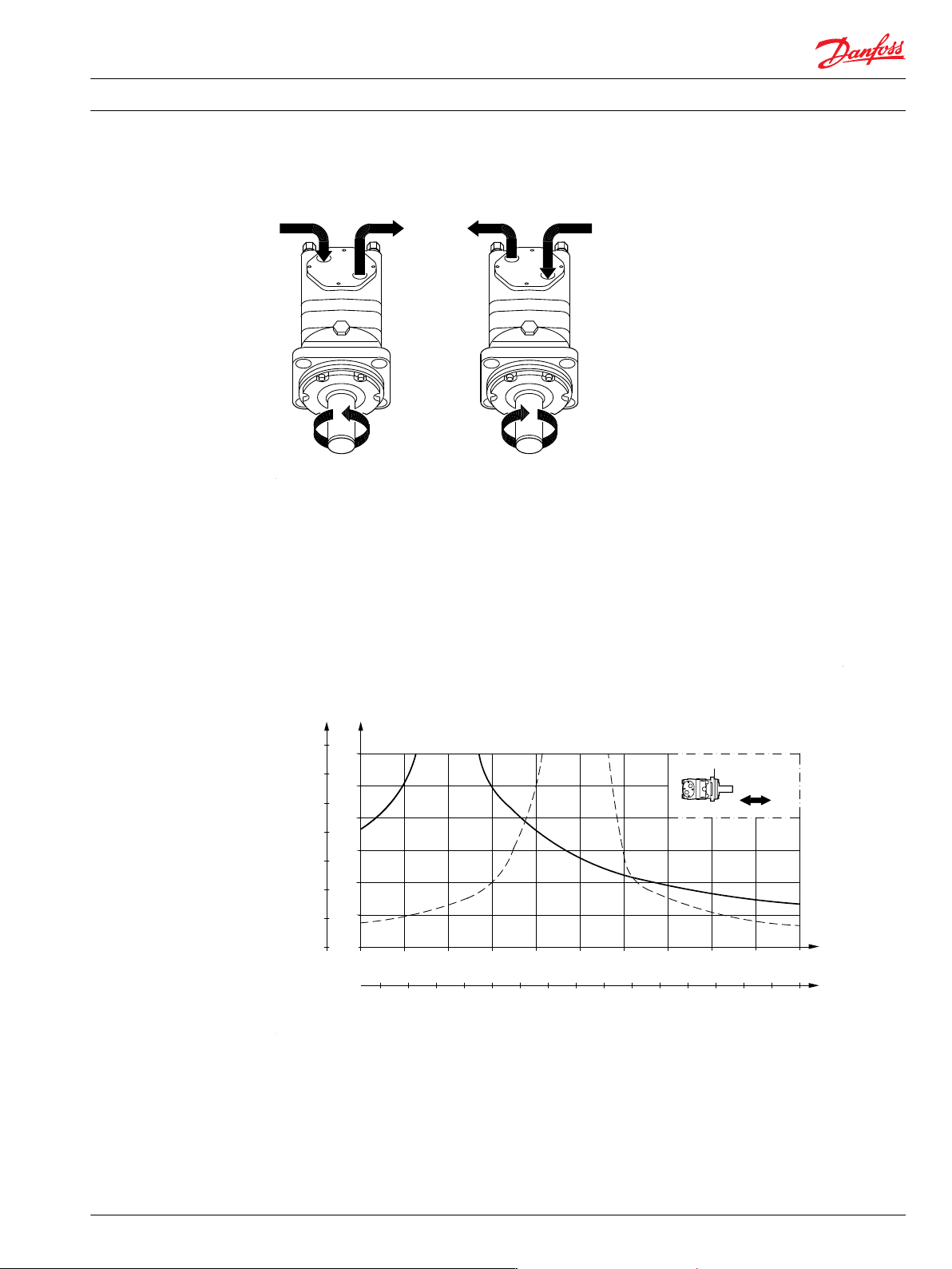
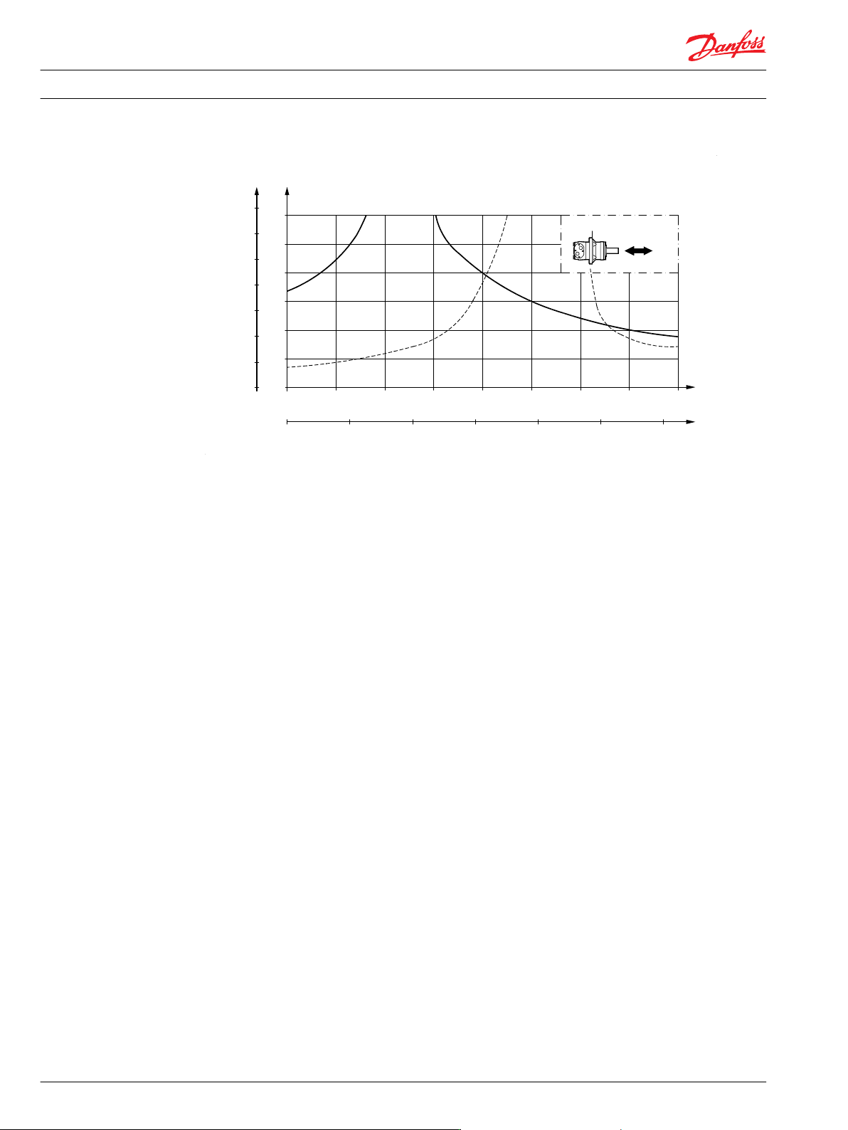
The output shaft runs in tapered roller bearings that permit high axial and radial forces.
The permissible radial load on the shaft is shown for an axial load of 0 N as a function of the distance from
the mounting flange to the point of load application.
The curve is based on B10 bearing life (2000 hours or 12,000,000 shaft revolutions at 100 min
-1
) at rated
output torque, when mineral-based hydraulic oil with a sufficient content of anti-wear additives, is used.
For 3,000,000 shaft revolutions or 500 hours – increase these shaft loads with 52%.
The dash curve shows maximum radial shaft load. Any shaft load exceeding the values shown in the
curve will involve a risk of breakage.
Bearing life calculations can be made using the explanation and formula provided in the chapter "Bearing
dimensioning" in the technical information "General Orbital motors" 520L0232.
Mounting flange:
Brake-wheel
Shaft:
All shaft types
Technical Information
OMS, OMT and OMV Orbital Motors
OMT
52 520L0407 • Rev 0601 • February 2016