WAAAF_ES_IA.pdf - 第31页
Type L max mm [in] L 1 * mm [in] L 2 mm [in] OMTS 250 157 [6.18] 27.8 [1.094] 107 [4.21] OMTS 315 166 [6.54] 37.0 [1.457] 116 [4.57] OMTS 400 177 [6.97] 47.5 [1.870] 127 [5.00] OMTS 500 191 [7.52] 61.5 [2.421] 142 [5.59]…
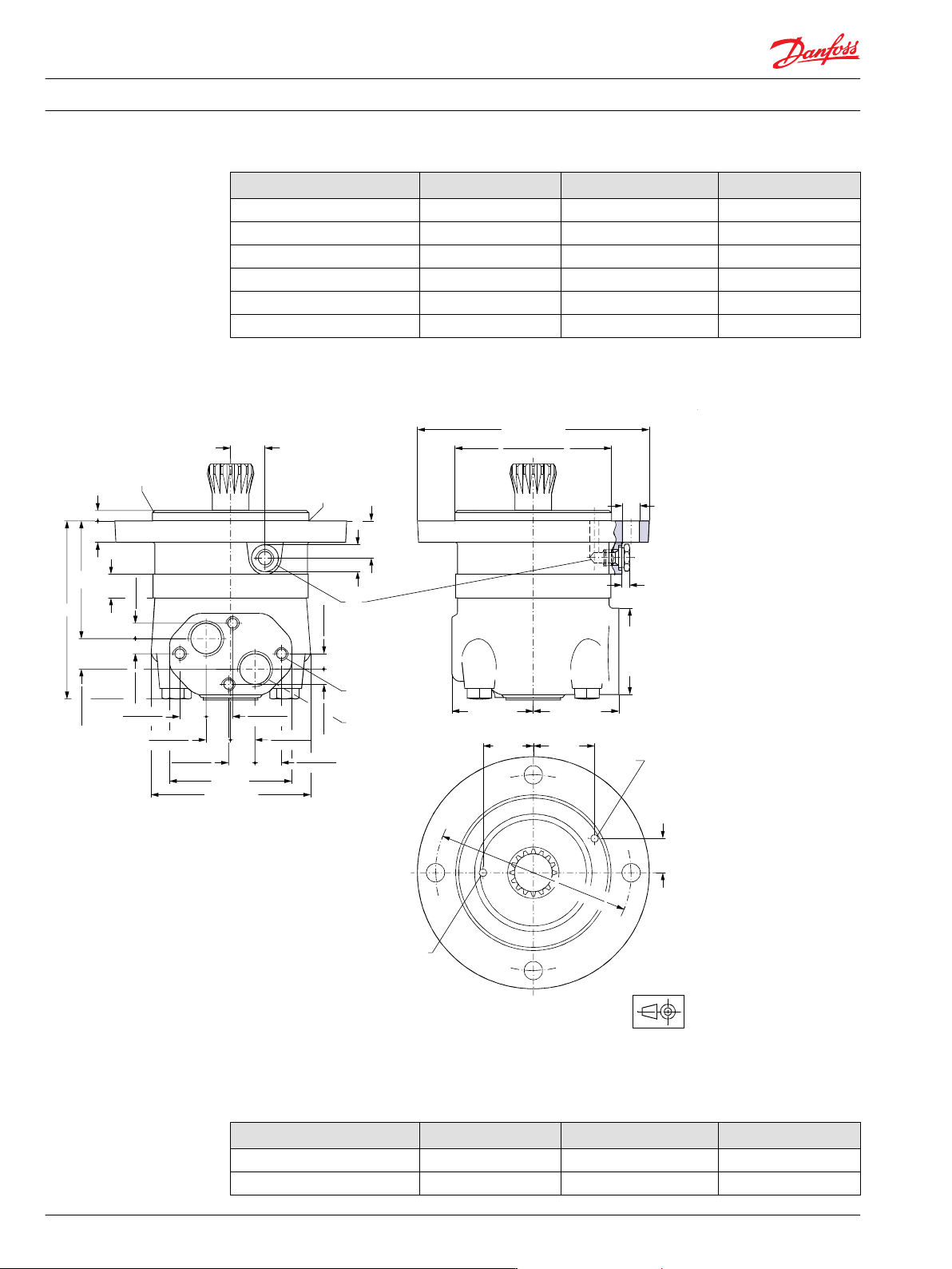
Type L
max
mm [in] L
1
*
mm [in] L
2
mm [in]
OMT 160 FL/FH 228 8.98] 16.5 0.650] 178 7.01]
OMT 200 FL/FH 233 [9.17] 21.5 0.846] 183 7.20]
OMT 250 FL/FH 239 [9.41] 27.8 [1.094] 189 7.44]
OMT 315 FL/FH 248 9.76] 37.0 1.457] 199 [7.83]
OMT 400 FL/FH 259 10.20] 47.5 1.870] 209 [8.23]
OMT 500 FL/FH 273 [10.75] 61.5 2.421] 223 [8.78]
*
The gearwheel set is 3.5 mm [0.138 in] wider across the rollers than the L1 dimensions
Short—European version
Ø125.000 [4.9213]
Ø124.937 [4.9188]
Ø14 [0.55]
max. Ø186 [7.32]
42 [1.65] 50 [1.97]
Ø6 [0.24]
Ø6 [0.24]
Ø160.4 [6.315]
Ø159.6 [6.283]
28 [1.10]
max. 69 [2.72]
22 [0.87]
1 [0.04]x45˚
23.6 [0.926]
22.4 [0.882]
13 [0.512]
12 [0.472]
13 [0.512]
12 [0.472]
13 [0.512]
12 [0.472]
13 [0.512]
12 [0.472]
R1 [0.04]
18 [0.71]
31 [1.22]
max. 71 [2.80]max. 67 [2.64]
8 [0.31]
8 [0.31]
28 [1.10]
151-898.11
22.1 [0.870]
21.1 [0.831]
22.1 [0.870]
21.1 [0.831]
22.1 [0.870]
21.1 [0.831]
22.1 [0.870]
21.1 [0.831]
20.3 [0.799]
19.7 [0.776]
20.3 [0.799]
19.7 [0.776]
100 [3.94]
max. 128 [5.04]
C
E
D
L
L
1
L
2
C: Drain connection G 1⁄4; 12 mm [0.47 in] deep
D: M10; 10 mm [0.39 in] deep E: G 3⁄4; 17 mm [0.67 in] deep
Type L
max
mm [in] L
1
*
mm [in] L
2
mm [in]
OMTS 160 146 [5.75] 16.5 [0.650] 96 [3.78]
OMTS 200 151 [5.94] 21.5 [0.846] 101 [3.98]
Technical Information OMS, OMT and OMV Orbital Motors
OMT
72 520L0407 • Rev 0601 • February 2016
Type L
max
mm [in] L
1
*
mm [in] L
2
mm [in]
OMTS 250 157 [6.18] 27.8 [1.094] 107 [4.21]
OMTS 315 166 [6.54] 37.0 [1.457] 116 [4.57]
OMTS 400 177 [6.97] 47.5 [1.870] 127 [5.00]
OMTS 500 191 [7.52] 61.5 [2.421] 142 [5.59]
*
The gearwheel set is 3.5 mm [0.138 in] wider across the rollers than the L1 dimensions
OMTS
Installation
The cardan shaft of the OMTS motor acts as an “output shaft”. Because of the movement of the shaft, no
seal can be fitted at the shaft output.
Internal oil leakage from the motor will therefore flow into the attached component.
During start and operation it is important that the spline connection and the bearings in the attached
component receive oil and are adequately lubricated. To ensure that the spline connection receives
sufficient oil, a conical sealing ring between the shaft of the attached component and the motor
intermediate plate is recommended. This method is used in the OMT.
The conical sealing ring (code. no. 633B9022) is supplied with the motor.
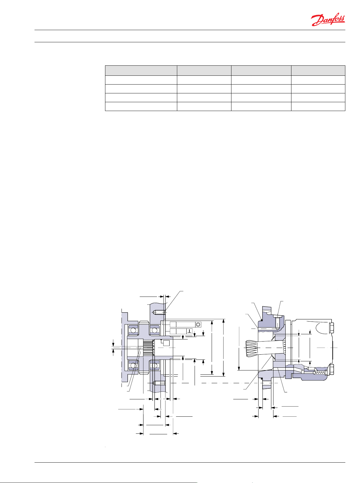
To ensure that oil runs to the bearings and other parts of the attached component, the stop plate must
have a hole in it (see fig. below).
We recommend an O-ring between motor and attached component. The O-ring (code no. 151B1040) is
supplied with the motor. If motor and attached component have been separated, remember to refill
before starting up. Fill the oil through the drain connection.
Attached component dimensions
OMTS dimensions of the attached component in millimeter [inches]
2.35 [0.093]
2.25 [0.089]
0.25 [0.010]
0.1˚
2.5 [0.098]
1.5 [0.059]
25.5 [1.004]
24.5 [0.965]
46.3 [1.823]
45.7 [1.799]
69.4 [2.732]
68.6 [2.701]
11.4 [0.449]
11.0 [0.433]
8.2 [0.323]
7.8 [0.307]
18.5 [0.728]
17.5 [0.689]
30 [1.181]
29 [1.142]
151-452.10
min. 5 [0.2]
min. Ø6 [0.24]
Ø125.063 [4.9237]
Ø125.000 [4.9212]
min. Ø55 [2.17]
Ø133.0 [5.236]
Ø132.6 [5.220]
Ø51.5 [2.028]
Ø50.5 [1.988]
39.5 [1.555]
38.5 [1.516]
Ø88.5 [3.484]
Ø87.5 [3.445]
Ø53.5 [2.106]
Ø53.5 [2.098]
Ø63.5 [2.500]
Ø62.5 [2.461]
C
A
B
E
D
F
K
K
K
G
H
Technical Information
OMS, OMT and OMV Orbital Motors
OMT
520L0407 • Rev 0601 • February 2016 73

A O-ring: 125 × 3 mm B External drain channel
C Drain connection
G 1⁄4; 12 mm [0.47 in] deep
D Conical seal ring
E Internal drain channel F M12; min. 18 mm [0.71 in] deep
G Oil circulation hole H Hardened stop plate
Attached component internal splines
The attached component must have internal splines corresponding to the external splines on the motor
cardan shaft (see the following drawing).
Material:
Case hardening steel with a tensile strength corresponding at least to 20 MoCr4 (900 N/mm
2
) or SAE
8620.
Hardening specification:
•
On the surface: HV = 750 ± 50
•
0.7 ± 0.2 mm under the surface: HV = 560
Internal involute spline data; Standard ANS B92.1-1970, class 5 (corrected m · X = 1; m = 2.1166)
Flat root side fit mm in
Number of teeth z 16 16
Pitch DP 12/24 12/24
Pressure angle 30° 30°
Pitch dia. D 33.8656 1.3333
Major dia. D
ri
38.4
0
+0.4
1.5118
0
+0.0157
Form dia. (min.) D
fi
37.6 1.4803
Minor dia. D
i
32.150
0
+ 0.04
1.2657
0
+ 0.00157
Space width (circular) L
o
4.516
±0.037
0.1777
±0.0014
Tooth thickness (circular) S
o
2.170 0.0854
Fillet radius R
min.
0.5 0.02
Max. measurement between pins
*
l 26.9
0
+ 0.1
1.059
0
+0.004
Pin dia. d 4.834
±0.001
0.1903
±0.00004
*
Finished dimensions (when hardened).
Technical Information OMS, OMT and OMV Orbital Motors
OMT
74 520L0407 • Rev 0601 • February 2016