00193356-02.pdf - 第29页
SIPLACE S-25 HM 2 Assembly Instructions: Component Sensor (Option) for RV12-DLM1 Placement Head 04/2007 Edition 2.4 Safety Instructions 29 2.4 Safety Instructions WA R N I N G Comply with the higher ranking "Safety …

2 Assembly Instructions: Component Sensor (Option) for RV12-DLM1 Placement Head SIPLACE S-25 HM
2.3 Overview of Assembly 04/2007 Edition
28
2.3.2 Prerequisites for Assembly
– Platform 2 (S-25 HM / HS-50)
– 12-DLM1 placement head
– Optional "modular head PCB" (is always assemblied on all gantries).
– Line computer software: line computer UNIX SW version 5.03.xx or later or SIPLACE PRO 1.3
– Station computer software HS-50 or S-25 HM: SW version 5.03.xx or later
NOTE:
Before assembling, find out what the machine is equipped with. 2
2.3.3 Required Time
-
Assembling the modular head PCB, PER placement head
Mechanical work + track signals + firmware download for head PCB approx. 1.5 hrs.
(of which, 0.5 hrs per placement head are for mechanical work)
- Assembling the component sensor, PER placement head:
Complete sequence, including trial placement approx.1.5 hrs.
(of which, 0.5 hrs per placement head are for mechanical work)
- Installation of SW V 503.xx on line computer and station computer approx. 3.0 hrs.
NOTE:
The modular head PCB must always be assemblied on ALL gantries (placement heads). 2

SIPLACE S-25 HM 2 Assembly Instructions: Component Sensor (Option) for RV12-DLM1 Placement Head
04/2007 Edition 2.4 Safety Instructions
29
2.4 Safety Instructions
WARNING
Comply with the higher ranking "Safety Instructions" in Chapter "Operational Safety" in the User
Manual and Service Manual. 2
The placement machines SIPLACE are powered by mains voltage.
Portions of the system are therefore conducting dangerous electricity, inside the machine even
while the master switch is turned off.
Death, serious injury or considerable damage may result if these automatic placement systems
are handled incorrectly.
After you have properly carried out the shut-down of the operating system:
Before all work the machine must be turned off at the main switch and isolated from the mains. In
addition, the compressed air supply must be turned off at the main valve of the compressed air
unit in the machine base and the compressed air lines must be bled by actuating the needle valve
at the compressed air unit.
Danger: For anyone wearing a heart pacemaker it is not permitted to work near linear motors, as
described in detail in the User Manual and the Service Manual, Chapter "Special Safety Instruc-
tions when working in vivinty of powerful magnetic fields" .
Obey the applicable accident prevention regulations, DIN standards and special safety codes of
your country at all times. DIN EN 60204 must be adhered to during all work inside the machine
base.
Follow the instructions regarding residual voltages in Chapter "Operational Safety".
Comply with regulations on ESDs (see Chapter "Operational Safety").
During the work of retrofitting secure the machine conscientiously against other personnel and
prevent it from being turned back on without authorization, as described in the User Manual in the
chapter "Locking the Machine...".
There is additional, higher risk of accident when working with the SITEST program.
The SITEST program is only to be started by personnel who are authorized to do so. 2
2
2 Assembly Instructions: Component Sensor (Option) for RV12-DLM1 Placement Head SIPLACE S-25 HM
2.4 Safety Instructions 04/2007 Edition
30
2.4.1 Safety Instructions for Laser Radiation
CAUTION
The component sensor is in accordance with Laser Class 1 when it is properly installed in the ma-
chine and is in undamaged condition. The light beam is spatially limited on the receiver side. 2
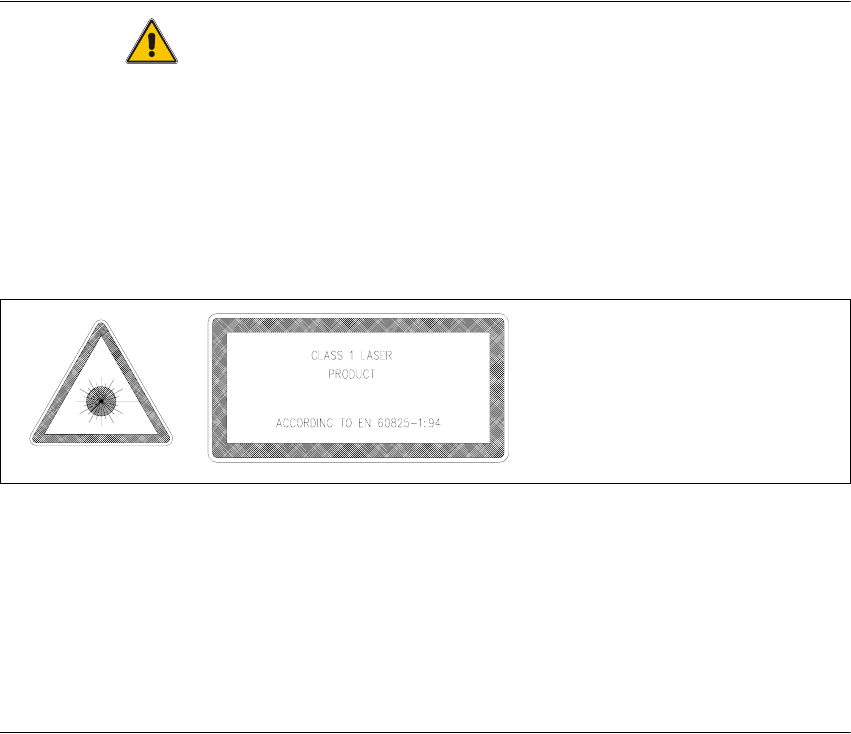
With this laser class, no laser warning signs are required on the machine (on the safety hoods) or
on the component sensor itself. It is sufficient if the signs identifying the laser class "1" in the
User Manual, as shown below.
Abb. 2.4.1 Laser Warning Signs in the User Manual in the Pertinent Language
If the component sensor is damaged or manipulated, it is not permissible to install/continue ope-
rating it. The component sensor is operated with +5 V and is not integrated into the safety circuit.
Rules for Germany:
Observe the guidelines of the Main Association of the German Trade Association, VBG 93.
In all other countries, comply with the pertinent guidelines and standards of the specific countries
in question. Standards to be observed: IEC 60825-1, EN 60825-1.
2