00193356-02.pdf - 第40页
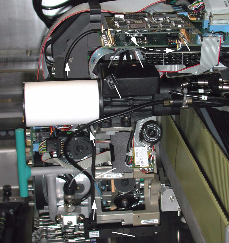
2 Assembly Instructions: Component Sensor (Opti on) for RV12-DLM1 Placement Head SIPLACE S-25 HM 2.6 Work Sequence 04/2007 Edition 40 2.6.3 HS-50: Laying Cable and Making Connections Abb. 2.6.5 HS-50: Laying and Connecti…
SIPLACE S-25 HM 2 Assembly Instructions: Component Sensor (Option) for RV12-DLM1 Placement Head
04/2007 Edition 2.6 Work Sequence
39
Now proceed as follows to ensure that the component sensor is not subjected to any strain when
installed: 2
: From the bottom of the sensor, exert a slight upward pressure in the position at the middle of
the assembling gauge (see Abb. 2.6.4 -> 3) such that the sensor incl. the assembling gauge is
in contact with the machined surface of the placement head. While doing so, slide the sensor
against the side mounting surface of the placement head to the stop and hold the sensor in this
position.
: In this position first tighten the screws on the side, then the screw on the bottom of the sensor.
In each case, follow the instructions regarding the torque (see Abschn. 2.5.6).
: Afterwards, while you are pulling out the assembling gauge, check how it moves (quickly, too
easily, with too much difficulty) to tell whether you installed the sensor correctly, i.e., it is not
under any strain:
– Correct installation:
The gauge can be pulled out quickly and evenly at all points, i.e., with noticeable vertical
clearance. Max. clearance = 0.1 mm
– Incorrect installation:
- There is a noticeable vertical clearance (> 0.1 mm) when the gauge is pulled out.
- The gauge clamps while being pulled out = vertical clearance is too small everywhere or
at some points.
: If, while pulling out the assembling gauge, you notice that the sensor is installed such that it is
being subjected to strain (has too much or too little clearance), loosen all 3 of the screws on
the sensor and repeat the entire adjustment process, as described above.
: Refasten the blast air unit onto the placement head:
1 socket hex head cap screw M3 (size 2.5).
Follow the instructions regarding to the torque (see Abschn. 2.5.6).
2 Assembly Instructions: Component Sensor (Option) for RV12-DLM1 Placement Head SIPLACE S-25 HM
2.6 Work Sequence 04/2007 Edition
40
2.6.3 HS-50: Laying Cable and Making Connections
Abb. 2.6.5 HS-50: Laying and Connecting the Component Sensor Cable
Key
1. Component sensor (assembly complete)
2. Route of component sensor cable to the gantry head distributor (on HS-50 and S-25 HM)
3. 1 cable tie (position on HS-50 and S-25 HM)
4. Route of cable under the gantry head distributor -> Detail: see Abb. 2.6.6)
5. Plug-in connector for round cable (motor/tachometer), drawn
6. 1 cable tie on the spacer bolt -> Detail: see Abb. 2.6.6)
7. Plug-in connector of the component sensor cable -> Detail: see Abb. 2.6.6)
2
1
2
1
2
2
2
6
5
7
3
4
SIPLACE S-25 HM 2 Assembly Instructions: Component Sensor (Option) for RV12-DLM1 Placement Head
04/2007 Edition 2.6 Work Sequence
41
: Unplug the connector of the round cable (motor/tachometer) on the modular head PCB (see
Abb. 2.6.5 -> 5).
: Lay the component sensor cable upward toward the modular head PCB and fasten the cable
in the BOTTOM cable run on the placement head, as shown in Abb. 2.6.5 -> 2 and 3.
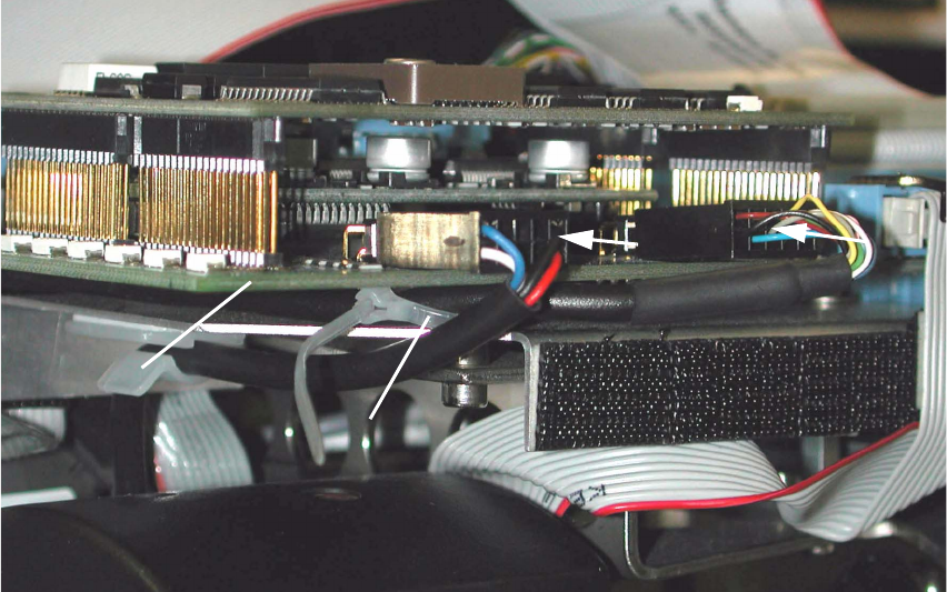
Abb. 2.6.6 HS-50, Modular Head PCB: Detail of Cable Fasteners and Plug-In Connector
Key:
1. Gantry head distributor HS-50, modular
2. Cable tie, fastener on spacer bolt
3. Plug-in connector of the component sensor cable
4. Plug-in connector of the round cable (motor/tachometer)
: Preshape the cable tie into an arch and thread it in around the spacer bolt (see Abb. 2.6.6 ->
2) located under the gantry head distributor, modular
: Run the component sensor cable under the PCB and back to the front, upstream of the spacer
bolt, and then out, as shown in Abb. 2.6.5 and Abb. 2.6.6.
: Make the plug-in connection of the component sensor cable on the gantry head distributor (see
Abb. 2.6.6 -> 3).
: Fasten the component sensor cable with cable tie to the spacer bolt (see Abb. 2.6.6 -> 2) in
such a manner that the strain on the plug-in connector is relieved but no large loop is created.
2
4
3
2
1