00193356-02.pdf - 第37页
SIPLACE S-25 HM 2 Assembly Instructions: Component Sensor (Option) for RV12-DLM1 Placement Head 04/2007 Edition 2.6 Work Sequence 37 : Undo the screw fastening the bl ast air unit (see Ab b. 2.6.2 -> 1) , to create ac…
2 Assembly Instructions: Component Sensor (Option) for RV12-DLM1 Placement Head SIPLACE S-25 HM
2.6 Work Sequence 04/2007 Edition
36
: If a head crash protection unit has been installed, fold it down now.
: Make certain that the Z-axis is at the top. Holding the placement head to be assemblied by the
handle, move it forward into a good working position.
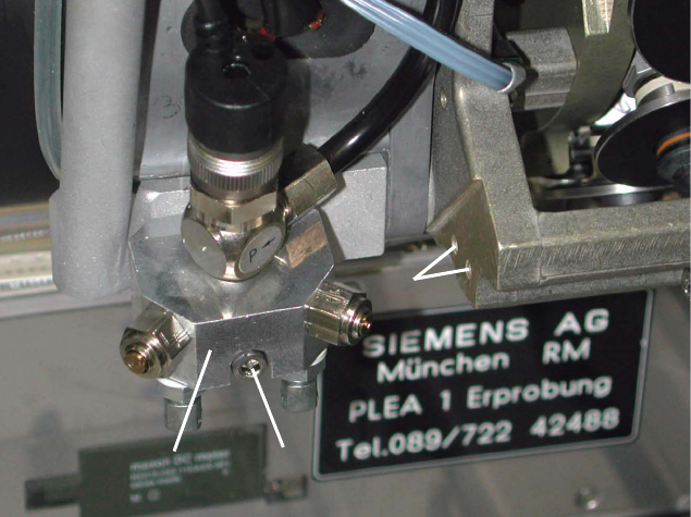
Abb. 2.6.2 Undo the Screw Fastening the Blast Air Unit, Holes to fasten the Sensor
Key:
1. Blast air unit
2. Screw fastening the blast air unit: 1 socket hex head cap screw M3 (size 2.5)
3. Screw holes to fasten the component sensor
: S-25 HM: Remove the protective cover (= currently one-piece) over the placement head, so
that the areas required for the assembling are accessible (undo 5 socket hex head cap screws
M3).
Currently, there is no protective cover on the HS-50.
2
2
2
2
2
2
2
1
2
1
2
3
SIPLACE S-25 HM 2 Assembly Instructions: Component Sensor (Option) for RV12-DLM1 Placement Head
04/2007 Edition 2.6 Work Sequence
37
: Undo the screw fastening the blast air unit (see Abb. 2.6.2 -> 1), to create access to the side
mounting holes (-> 3) for the component sensor:
Undo 1 socket hex head cap screw M 3 (-> 2).
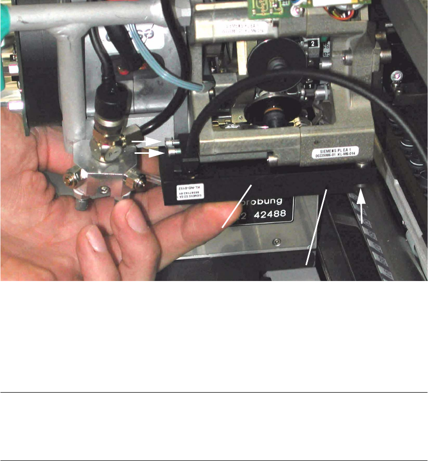
Abb. 2.6.3 Fastening the Component Sensor (HS-50 / S-25 HM)
Key:
1. Component sensor
2. 2 socket hex head cap screws M3 (short), from assembly kit (do not tighten yet)
3. 1 socket hex head cap screw M3 (long), from assembly kit (do not tighten yet)
NOTE:
In the hole for the component sensor (see Abb. 2.6.3 -> 3) there is a sleeve that is flexible in a
longitudinal direction. It is used together with the assembling gauge for a strain-free assembly
(see Abb. 2.6.4 -> 2). 2
: Holding the component sensor as shown above, place it on the placement head to the stop
from below.
: Pull the blast air unit away slightly with one hand. The silicone hose on the bottom is not to kink
during this process.
2
3
2
1
1
3
2
(Control LED)
2 Assembly Instructions: Component Sensor (Option) for RV12-DLM1 Placement Head SIPLACE S-25 HM
2.6 Work Sequence 04/2007 Edition
38
: First, screw the two short socket hex head cap screws M3 into the side of the component sen-
sor (see Abb. 2.6.3 -> 3), but do not tighten the screws all the way yet.
: If the head crash protection unit has been installed, move the placement head (by the handle)
until it is over the gap between the protection unit and the empty-tape duct so that you can in-
sert the screw from the bottom of the sensor (see Abb. 2.6.3 -> 3).
: From the bottom, screw in the long socket hex head cap screw M3 (see Abb. 2.6.3 -> 2), but
do not tighten the screw all the way yet.
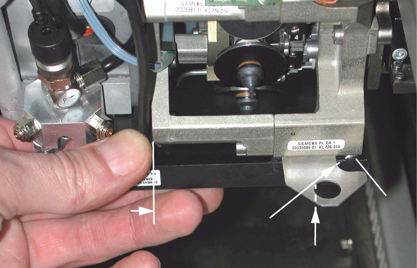
Abb. 2.6.4 Inserting the Assembling Gauge and Tightening the Component Sensor Screws
Key:
1. Component sensor, on the side, on the stop on the placement head
2. Sleeve in the component sensor, mounted such that it is axially flexible
3. Direction in which the assembling gauge (from the assembly kit) is slide in diagonally
4. Component sensor, contacted by a slight upward pressure at the middle of assembling gauge
: Now slide the assembling gauge between placement head and component sensor to the
sleeve as far as the stop (-> see figure above, position 3), such that the radius of the gauge is
in complete contact around the circumference of the sleeve.
2
2
1
4
3