00193356-02.pdf - 第36页
2 Assembly Instructions: Component Sensor (Opti on) for RV12-DLM1 Placement Head SIPLACE S-25 HM 2.6 Work Sequence 04/2007 Edition 36 : If a head crash protection unit has been inst alled, fold it down now . : Make certa…
SIPLACE S-25 HM 2 Assembly Instructions: Component Sensor (Option) for RV12-DLM1 Placement Head
04/2007 Edition 2.6 Work Sequence
35
2.6.2.1 HS-50 and S-25 HM: Mounting the Component Sensor on the Placement Head
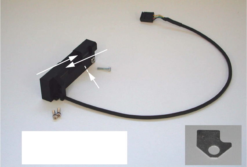
Abb. 2.6.1 Assembly Kit: Component Sensor incl. Screws and Assembling Gauge
2
2
2
2
2
2
2
2
2
2
2
2
2
2
Transmitter
Receiver
Do not touch transmitter or
receiver area!
Do not unpack sensor until just
before installation!
Control LED
Assembling gauge
2 Assembly Instructions: Component Sensor (Option) for RV12-DLM1 Placement Head SIPLACE S-25 HM
2.6 Work Sequence 04/2007 Edition
36
: If a head crash protection unit has been installed, fold it down now.
: Make certain that the Z-axis is at the top. Holding the placement head to be assemblied by the
handle, move it forward into a good working position.
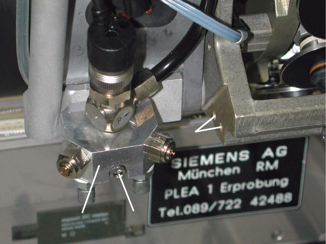
Abb. 2.6.2 Undo the Screw Fastening the Blast Air Unit, Holes to fasten the Sensor
Key:
1. Blast air unit
2. Screw fastening the blast air unit: 1 socket hex head cap screw M3 (size 2.5)
3. Screw holes to fasten the component sensor
: S-25 HM: Remove the protective cover (= currently one-piece) over the placement head, so
that the areas required for the assembling are accessible (undo 5 socket hex head cap screws
M3).
Currently, there is no protective cover on the HS-50.
2
2
2
2
2
2
2
1
2
1
2
3
SIPLACE S-25 HM 2 Assembly Instructions: Component Sensor (Option) for RV12-DLM1 Placement Head
04/2007 Edition 2.6 Work Sequence
37
: Undo the screw fastening the blast air unit (see Abb. 2.6.2 -> 1), to create access to the side
mounting holes (-> 3) for the component sensor:
Undo 1 socket hex head cap screw M 3 (-> 2).
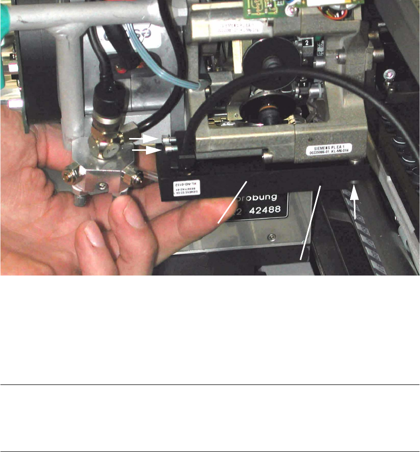
Abb. 2.6.3 Fastening the Component Sensor (HS-50 / S-25 HM)
Key:
1. Component sensor
2. 2 socket hex head cap screws M3 (short), from assembly kit (do not tighten yet)
3. 1 socket hex head cap screw M3 (long), from assembly kit (do not tighten yet)
NOTE:
In the hole for the component sensor (see Abb. 2.6.3 -> 3) there is a sleeve that is flexible in a
longitudinal direction. It is used together with the assembling gauge for a strain-free assembly
(see Abb. 2.6.4 -> 2). 2
: Holding the component sensor as shown above, place it on the placement head to the stop
from below.
: Pull the blast air unit away slightly with one hand. The silicone hose on the bottom is not to kink
during this process.
2
3
2
1
1
3
2
(Control LED)