00193356-02.pdf - 第35页
SIPLACE S-25 HM 2 Assembly Instructions: Component Sensor (Option) for RV12-DLM1 Placement Head 04/2007 Edition 2.6 Work Sequence 35 2.6.2.1 HS-50 and S-25 HM: Mounting the Comp onent Sensor on the Placement Head Abb. 2.…

2 Assembly Instructions: Component Sensor (Option) for RV12-DLM1 Placement Head SIPLACE S-25 HM
2.6 Work Sequence 04/2007 Edition
34
2.6 Work Sequence
2.6.1 Preparatory Steps
: Undock the component trolley from the placement system.
2
: Use the function "gantry in setup position" to move the placement head(s) into the area over
the PCB conveyor.
: If the machine is fitted with a head crash protection unit, fold it up.
: If you assembly the option on a number of placement heads, keep in mind:
You must maintain the existing allocation of the mobile changeover table to the locations 1-4.
: Undock the mobile changeover table(s) from the machine and move it out of the machine.
: Turn the machine OFF and disconnect the machine from the mains.
: If you haven’t already done so, assembly the modular head PCB on each gantry of the PCB
as described in the assembly instructions for modular head PCB on S-23, S-25 HM, F5 HM,
HS-50", item no.: 00192393-01, G + E.
2.6.2 Installing the Assembly Kit
CAUTION
Comply with the ESD regulations while handling the PCBs.
Use the ESD bracelet and connect it to the grounding button on the machine that is provided for
this purpose.
Make certain that NO screws or other parts drop into the machine or the placement head. 2
SIPLACE S-25 HM 2 Assembly Instructions: Component Sensor (Option) for RV12-DLM1 Placement Head
04/2007 Edition 2.6 Work Sequence
35
2.6.2.1 HS-50 and S-25 HM: Mounting the Component Sensor on the Placement Head
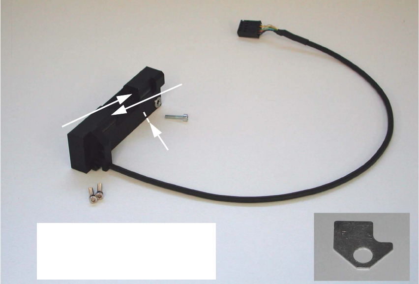
Abb. 2.6.1 Assembly Kit: Component Sensor incl. Screws and Assembling Gauge
2
2
2
2
2
2
2
2
2
2
2
2
2
2
Transmitter
Receiver
Do not touch transmitter or
receiver area!
Do not unpack sensor until just
before installation!
Control LED
Assembling gauge
2 Assembly Instructions: Component Sensor (Option) for RV12-DLM1 Placement Head SIPLACE S-25 HM
2.6 Work Sequence 04/2007 Edition
36
: If a head crash protection unit has been installed, fold it down now.
: Make certain that the Z-axis is at the top. Holding the placement head to be assemblied by the
handle, move it forward into a good working position.
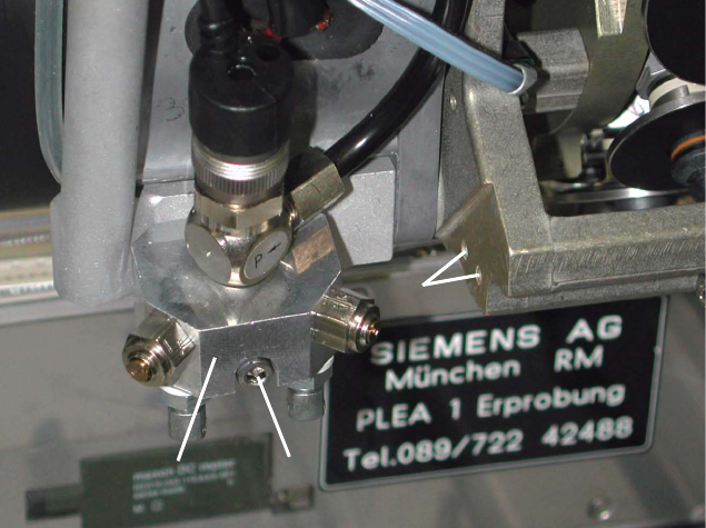
Abb. 2.6.2 Undo the Screw Fastening the Blast Air Unit, Holes to fasten the Sensor
Key:
1. Blast air unit
2. Screw fastening the blast air unit: 1 socket hex head cap screw M3 (size 2.5)
3. Screw holes to fasten the component sensor
: S-25 HM: Remove the protective cover (= currently one-piece) over the placement head, so
that the areas required for the assembling are accessible (undo 5 socket hex head cap screws
M3).
Currently, there is no protective cover on the HS-50.
2
2
2
2
2
2
2
1
2
1
2
3