Vista Machine PC.pdf - 第13页
MACHINE PC VISION CARD Chapter Issue 1 Sep 02 Technical Reference Manual 5.13 VISION CARD The card, fi tted to sl ot PCI 3, is a complete vi sion system, it utiliz es the machine CPU and Memory as it s control ler . The …

MACHINE PC
NEXTMOVE
5.12 Technical Reference Manual Chapter Issue 1 Sep 02
NEXTMOVE NextMove is installed in the PC enclosure. However, NextMove is a motion
controller and its functions are described fully in the Machine Controller chapter
of this manual.
The NextMove card sits on the ISA Bus and is itself controlled by the central
processor unit (CPU) in the PC enclosure. This arrangement allows the CPU
to control functions such as the operator interface (the MMI) and provide
general housekeeping functions along with general PC control whilst the Next-
Move card, with its own on-board CPU specifically controls all machine motion.
MACHINE PC
VISION CARD
Chapter Issue 1 Sep 02 Technical Reference Manual 5.13
VISION CARD
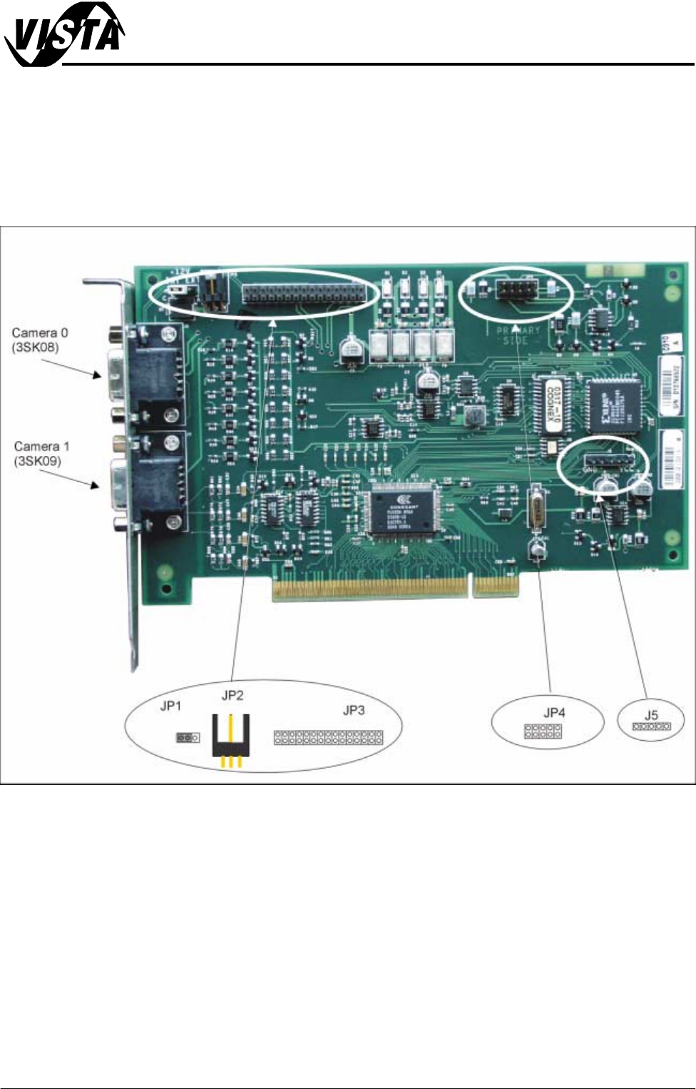
The card, fitted to slot PCI 3, is a complete vision system, it utilizes the machine
CPU and Memory as its controller.
The card takes the incoming signal from the camera, processes and returns a
fiducial location coordinate to the alignment algorithm.
Figure 5-5 Vision Card Layout
MACHINE PC
VISION PC ADAPTOR CARD
5.14 Technical Reference Manual Chapter Issue 1 Sep 02
VISION PC ADAPTOR CARD
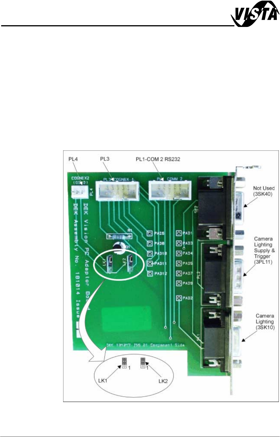
The Vision PC Adaptor Card is located in slot ISA 5 of the enclosure. The card
routes signals from the SBC Processor and the Vision Processor Cards to
control the camera lighting at the camera.
An on-board FET device (Q1) inverts the strobe signal from the vision processor
to condition the signal for compatibility with the control board input for the
camera lighting. 3PL11 feeds power on to the camera control board via links to
3SK10.
3SK10 is an RS232 Serial Communications link. Communications are estab-
lished between the vision processor and the camera control board. A serial
data stream is fed back from the control board to confirm that the correct camera
is being used and the set up data (if LED’s are switched on) is routed to the
camera lighting boards on the camera assembly.
Figure 5-6 Vision Adaptor Card Layout