Vista Machine PC.pdf - 第8页
MACHIN E PC PC ENCLOSURE 5.8 Technical Reference Manual Chapter Issue 1 Sep 02 CMOS Settings The foll owing t ables li st the CMOS s ettings fo r the machine. These set tings are based on A W ARD BIOS Revision 1.1 1. T o…
MACHINE PC
PC ENCLOSURE
Chapter Issue 1 Sep 02 Technical Reference Manual 5.7
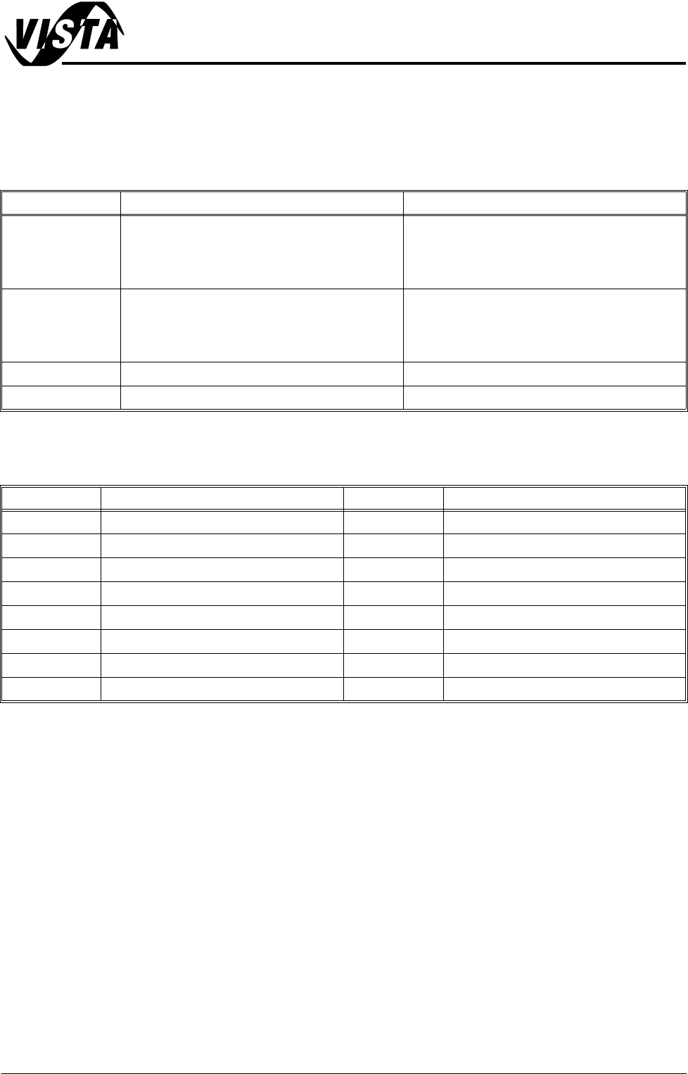
Jumper Link Function
CAUTION
JUMPER SETTINGS. Most settings are software selected, all jumpers are
factory set and should not be disturbed as board damage may occur.
Connector Function
Link Function Action / Set Position
J1 CMOS Clear Link can erase the CMOS data and reset the
system BIOS information:
Keep CMOS data - pins 1-2 linked together
Clear CMOS data - pins 2-3 linked together
J2 Watchdog Timer Output Resets the CPU or sends a signal to IRQ11 in the
event the CPU stops processing:
IRQ11 - pins 1-2 linked together
Reset - pins 2-3 linked together (default setting)
CN20 ATX Feature Connector Pins 2-3 linked together
CN22 H/W Monitor Alarm Pins 1-2 linked together enables OBS alarm
Connector Function Connector Function
3SK02 LAN Connector CN10 Serial Port COM 2 (Camera Lighting)
3SK04 P/S2 Keyboard CN16 Keyboard Lock and Power LED
3PL03 Serial Port: COM 1 (Touchscreen) CN17 External Speaker
3SK05 VGA Connector CN18 Reset Connector
3SK07 P/S2 Mouse CN19 HDD LED Connector
CN1 Primary IDE Connector CN20 ATX Feature Connector
CN3 Floppy Drive Connector CN22 H/W Monitor Alarm
CN4 Parallel Printer Port
MACHINE PC
PC ENCLOSURE
5.8 Technical Reference Manual Chapter Issue 1 Sep 02
CMOS Settings The following tables list the CMOS settings for the machine. These settings are
based on AWARD BIOS Revision 1.11.
To enter the CMOS Setup Utility press Del when prompted during the initial
phase of the system PC bootup sequence. To navigate the menu pages use
the cursor keys, to change a setting use Page Up and Page Down keys. To
save settings press F10 and confirm.
NOTE
Settings marked with a * are hardware dependent and are subject to change.
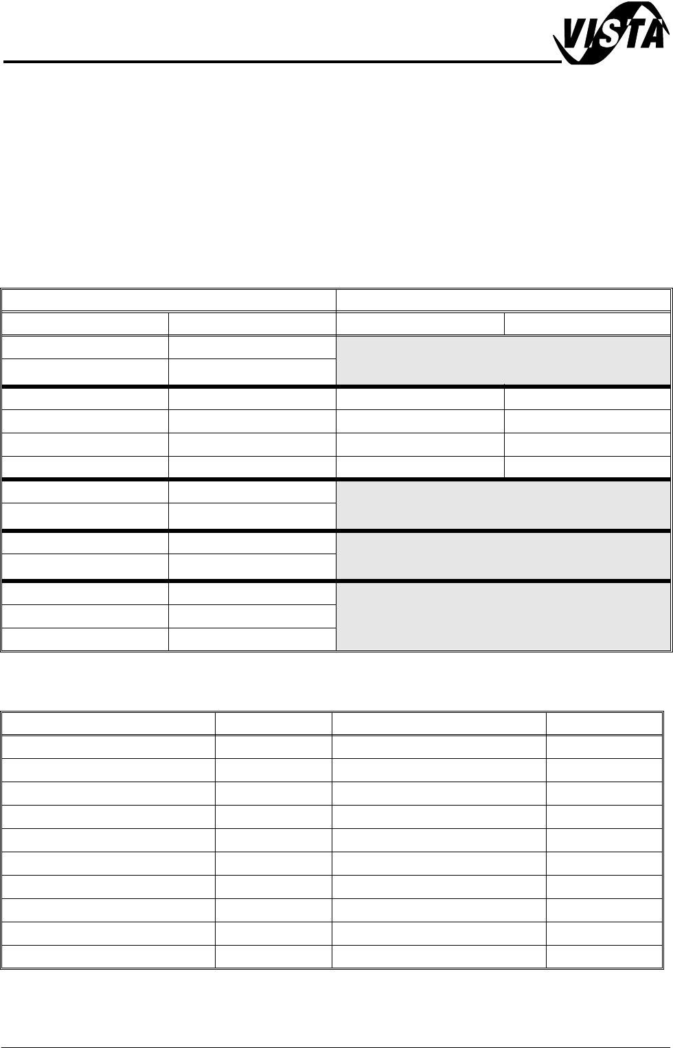
Standard CMOS Setup
Advanced BIOS Features
Menu Sub Menu
Feature Setting Feature Setting
System Date Current Date (mm:dd:yy)
Time Current Time (hh:mm:ss)
Primary Master Auto IDE Primary Master Auto
Primary Slave Auto IDE Primary Slave Auto
Secondary Master None IDE Secondary Master None
Secondary Slave None IDE Secondary Slave None
Drive A 1.44M, 3.5″
Drive B None
Video EGA/VGA
Halt On All Errors
Base Memory 640K
Extended Memory 130048K
Total Memory 131072K
Parameter Setting Parameter Setting
Virus Warning Disabled Swap Floppy Drive Disabled
CPU Internal Cache Enabled Boot Up Floppy Seek Enabled
External Cache Enabled Boot Up NumLock Status On
CPU L2 Cache ECC Checking Enabled Gate A20 Option Fast
Processor Number Feature Enabled Typematic Rate Setting Disabled
Quick Power On Self Test Enabled Typematic Rate (Char/Sec) 6
First Boot Device Floppy Typematic Delay (Msec) 250
Second Boot Device CDROM Security Option Setup
Third Boot Device HDD-0 OS Select For DRAM>64MB Non-OS2
Boot Other Device Enabled Report NO FDD For Win 95 No
MACHINE PC
PC ENCLOSURE
Chapter Issue 1 Sep 02 Technical Reference Manual 5.9
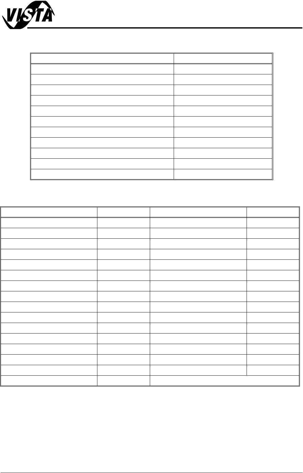
Advanced Chipset Features
Integrated Peripherals
Parameter Setting
SDRAM CAS Latency Time 3
SDRAM Cycle Time Trs/Trc 7/9
SDRAM RAS-to-CAS Delay 3
SDRAM RAS Precharge Time 3
System BIOS Cacheable Enabled
Video BIOS Cacheable Enabled
Memory Hole at 15M-16M Disabled
CPU Latency Timer Enabled
Delayed Transaction Enabled
AGP Graphics Aperture Size 64MB
On-Chip Video Window Size 64MB
Parameter Setting Parameter Setting
On-Chip Primary PCI IDE Enabled Onboard PCI SCSI Chip Disabled
On-Chip Secondary PCI IDE Disabled IDE HDD Block Mode Enabled
IDE Primary Master PI0 Auto Onboard FDC Controller Enabled
IDE Primary Slave PI0 Auto Onboard Serial Port 1 3F8/IRQ4
IDE Secondary Master PI0 Disabled Onboard Serial Port 2 2F8/IRQ3
IDE Secondary Slave PIO Disabled UART Mode Select Normal
IDE Primary Master UDMA Auto RxD, TxD Active Hi, Lo
IDE Primary Slave UDMA Auto IR Transmission Delay Enabled
IDE Secondary Master UDMA Disabled UR2 Duplex Mode Half
IDE Secondary Slave UDMA Disabled Use IR Pins IR-Rx2Tx2
USB Controller Enabled Onboard Parallel Port 378/IRQ7
USB Keyboard Support Enabled Parallel Port Mode EPP
Init Display First AGP EPP Mode Select EPP1.7
Onboard LAN BootROM Disabled ECP Mode USe DMA 3
Onboard 82562 LAN Chip Enabled Watch Dog Timer Select Disabled
Onboard 82559 LAN Chip Enabled