00195044-15_UM_VisionTeachStation_DE EN.pdf - 第117页
Vision Teach Station User Manual 4 Setting up the vision teach station 10/2015 Edition 4.3 Camera and CAN bus connections on the PC 117 4.3 Camera and CAN bus connections on the PC (1) 4 (2) 4 (3) 4 Fig. 4.3 - 2 Connecto…
4 Setting up the vision teach station Vision Teach Station User Manual
4.2 Connections and LED displays on the base module 10/2015 Edition
116
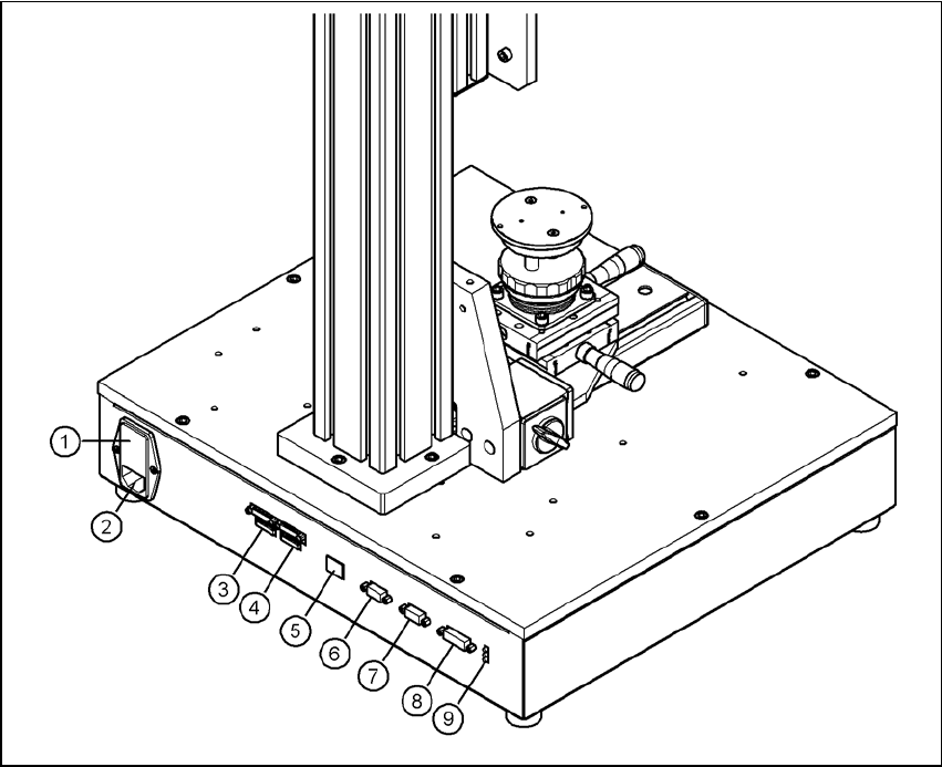
4.2 Connections and LED displays on the base module
4
Fig. 4.2 - 1 Connectors and LED displays on the base module
(1) Power switch and fuse holder for the 2.5 A fuse
(2) Power socket (110 VAC to 240 VAC)
(3) Connection for cable, head camera 1 (03040353-W1: 26-pin, 03040353-W2: 12-pin)
(4) Connection for cable, head camera 2 (03040353-W1: 26-pin, 03040353-W2: 12-pin)
(5) Connection for camera bus cable to the PC (03040359-xx) (only if head camera is installed)
(6) Connection for CAN bus cable to the PC (03040362-xx)
(7) Connection for CAN bus cable to the stationary camera (03040355-W2)
(8) Connection for the power supply cable for the stationary camera (03040355-W1)
(9) LED displays for supply voltages, from top to bottom:
+ 24 VDC- (red)
+ 15 VDC- (yellow)
+ 42 VDC- (green)
Vision Teach Station User Manual 4 Setting up the vision teach station
10/2015 Edition 4.3 Camera and CAN bus connections on the PC
117
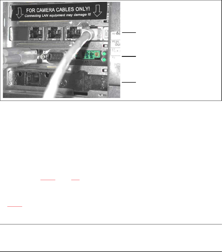
4.3 Camera and CAN bus connections on the PC
(1)
4
(2)
4
(3)
4
Fig. 4.3 - 2 Connectors and LED displays on the base module
(1) Camera bus interface with 4 connections
(2) CAN bus interface with 2 connectors
(3) SIPLACE LAN interface
4.4 Connecting the CAN bus between base module and PC
Connect the 3 m CAN bus cable (item no. 003040362-xx) to the connector on the base module
(item 6 in Fig. 4.2 - 1, page 116).
Tighten the two screws to secure the connector.
Plug the CAN bus cable into one of the two sockets on the CAN bus interface (item 2 in Fig.
4.3 - 2).
Tighten the two screws to secure the connector.
NOTE 4
The procedure for connecting the camera bus cable is described in the sections for the different
cameras.
5 Installing the cameras Vision Teach Station User Manual
5.1 Installing stationary cameras, type 25, 33 and 36 10/2015 Edition
118
5 Installing the cameras
The vision teach station is supplied with the ordered camera fully installed. The following sections
describe how to install the stationary cameras and the head cameras.
5.1 Installing stationary cameras, type 25, 33 and 36
The type 25, 33 and 36 stationary cameras can be installed on the following placement machines:
Component camera Placement machines
Type 25 (FC camera)
SX series, X-series, D1 and D3
Type 33 (IC camera)
SX series, X-series, D1 and D3
Type 36 (IC camera)
SX series, D1
Tab. 5.1 - 1 Stationary camera for the D and X-series
Installation of the stationary cameras is described with reference to camera type 33. Type 25 and
36 are installed in the same way. Only the coding switch settings are different.
WARNING 5
When you lift or carry the stationary camera, never hold it by the illumination head alone (item 1
in Fig. 5.1 - 1, page 119). The latching connection between the illumination head (item 1) and the
base module (item 2) could be broken by the weight of the base module (item 3 in Fig. 5.1 - 1,
page 119), causing the base module to fall off.
CAUTION 5
The plug-in illumination head (item 1 in Fig. 5.1 - 1) incorporates the illumination section that is
matched to the camera's CCD sensor. You should therefore never swap the illumination heads
between cameras. If you do, the cameras will no longer work.