00195044-15_UM_VisionTeachStation_DE EN.pdf - 第179页
Vision Teach Station User Manual 11 Measuring components 10/2015 Edition 11.2 Measuring the component 179 1 1.2 Measuring the component 1 1.2.1 General order for programming the PF The handling data must be programmed (n…
11 Measuring components Vision Teach Station User Manual
11.1 Preparing components for the measurement 10/2015 Edition
178
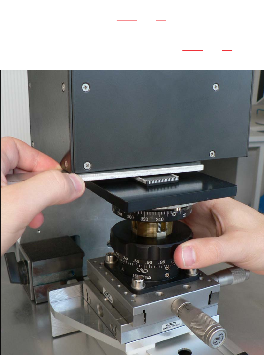
Push the positioning unit (item 2 in Fig. 11.1 - 1, page 177) until the end stop is under the
camera.
Lock the positioning unit (item 2 in Fig. 11.1 - 1, page 177) using the magnetic switch (item 1
in Fig. 11.1 - 1, page 177)
Check the camera image on the monitor and position the middle of the component at the
camera center point using the micrometer screw (item 3 in Fig. 11.1 - 1, page 177).
If necessary, turn the component so that the outer edges run parallel to the edge of the image.
11
Fig. 11.1 - 2 Setting the focus point with the adjustment guide
Vision Teach Station User Manual 11 Measuring components
10/2015 Edition 11.2 Measuring the component
179
11.2 Measuring the component
11.2.1 General order for programming the PF
The handling data must be programmed (nozzle assignment, etc) before the teaching takes place
at the station. It must be possible to pick up and center the component to be taught.
When teaching on the SIPLACE vision teach station, the handling data cannot be programmed
until the optical features have been programmed.
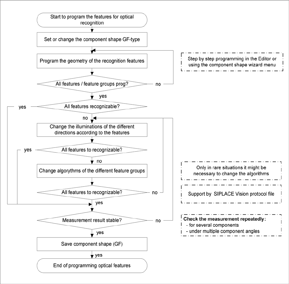
Fig. 11.2 - 3 Flow chart showing the PF programming sequence
11 Measuring components Vision Teach Station User Manual
11.2 Measuring the component 10/2015 Edition
180
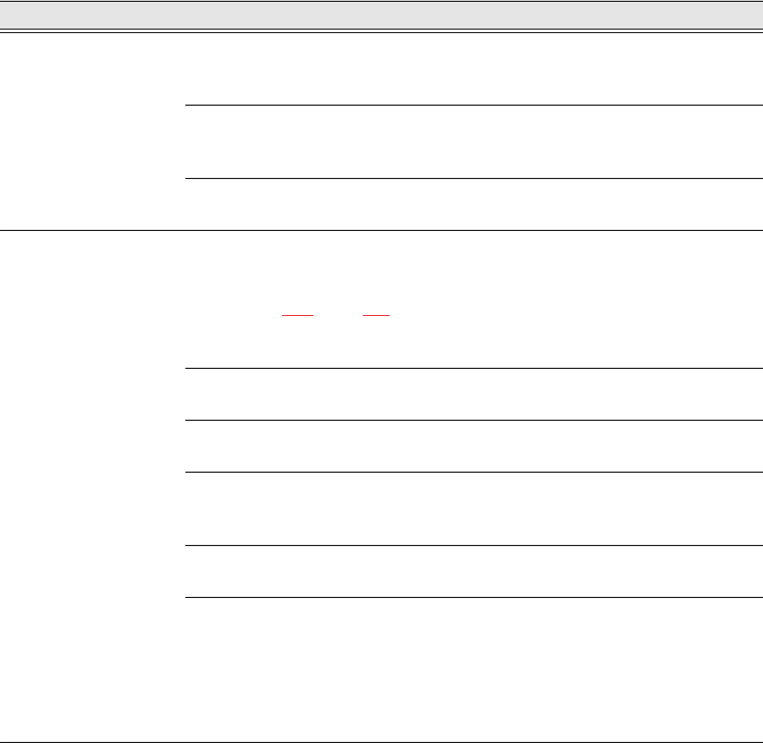
11.2.2 Programming steps with the vision teach station
The following table guides you through the individual steps for programming a package form.
We distinguish between three programming areas:
– The two areas of the SIPLACE Vision Teach Station software
accessed via the Start SIPLACE Pro and Measurement buttons.
– The SIPLACE Pro Desk programming interface
Programming area Action Detail / Special feature
SIPLACE vision teach
station button:
SIPLACE Pro
Selects the PF directory and the
prepared PACKAGE FORM.
Or recreate a PACKAGE FORM by right-
clicking in the free area.
Enter the required PF name in the dialog.
Enter the body dimension Z with
tolerance
(data sheet/ caliper gauge).
X/Y PF dimensions are changed at the vision
teach station.
Button: Geometry.
Enter comment about the package
form.
Can also be entered before programming in
SIPLACE Vision.
SIPLACE vision teach
station button:
Start measurement
Add the PF under the camera
(see section 11.1, page 175).
Move X/Y cross-bed with component in be-
neath the camera. Adjust the height with the
"focus gauge".
Switch on magnet and modify the X-Y positi-
on of the cross-bed so that the component
appears in the middle beneath the camera.
Start measurement
The camera image and the SIPLACE Vision
menus are displayed.
Select the Geometry button.
Select the appropriate package form type and
program the body dimensions.
Program connection geometry
Program the lead or ball/pillar geometry or the
corner/polygon circle for the groups concer
-
ned.
All contacts recorded?
Program the connections and repeat until all
the connection groups are recorded.
Pay particular attention to the tole-
rances (defaults when program-
ming) of the programmed set-
points.
Tolerances:
up to 30% is recommended in all package
form geometries;
over 40% (pin width) - the measuring algo-
rithms can be affected;
over 50% - not permitted.