00195044-15_UM_VisionTeachStation_DE EN.pdf - 第182页
12 Coordinate systems of the component cameras Vision Teach Station User Manual 11.2 Measuring the component 10/2015 Edition 182 12 Coordinate systems of the component cameras Representation of the preferred 0° position …
Vision Teach Station User Manual 11 Measuring components
10/2015 Edition 11.2 Measuring the component
181
Tab. 11.2 - 1 Programming steps with the vision teach station
Alternatively, all the programming can be prepared in SIPLACE Pro and then tested at the
SIPLACE vision teach station.
SIPLACE vision teach
station button:
Start measurement
Test PACKAGE FORM:
The optical centering should provide a stable
result. Tested with several components at
various angles.
Measurement failed? No: Save
Yes: Correct the geometry
or modify the illumination.
Measurement failed? No: Save
Yes: It may also be necessary to
modify the algorithm.
This is only necessary in exceptional circum-
stances.
PACKAGE FORM tested success-
fully (multiple times)?
No: Repeat previous menu
Yes: Save PACKAGE FORM
by switching to the SIPLACE Pro
menu.
SIPLACE Pro Desk
Programming of the
handling data; check with station
configuration
Assignment of nozzles; camera; reduced ac-
celeration of the axes; processing data; fee-
der type
Export PACKAGE FORM and
save to a memory stick.
Export data model
Import the PACKAGE FORM on
the SIPLACE Pro computer on the
line.
Import data model
Programming area Action Detail / Special feature
12 Coordinate systems of the component cameras Vision Teach Station User Manual
11.2 Measuring the component 10/2015 Edition
182
12 Coordinate systems of the component cameras
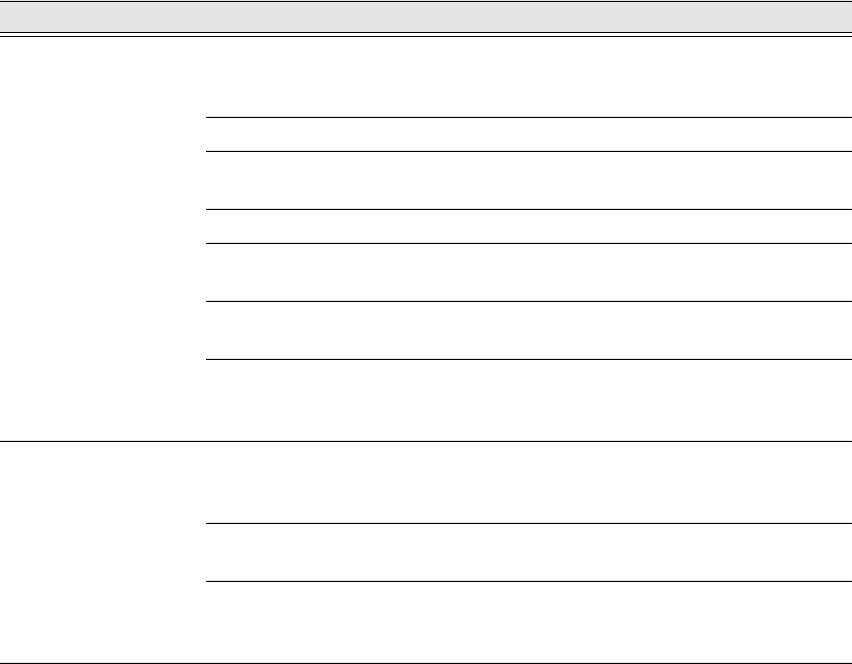
Representation of the preferred 0° position on the SIPLACE Pro computer and on the vision
teach station 12
The following illustrations show how the package form is represented in the preferred 0° position
on the SIPLACE Pro computer or on the SIPLACE vision teach station.
SIPLACE Pro computer
SIPLACE Vision Teach Station
12
Fig. 12.0 - 1 Representation of the preferred 0° position on the SIPLACE Pro computer and on the vision teach station
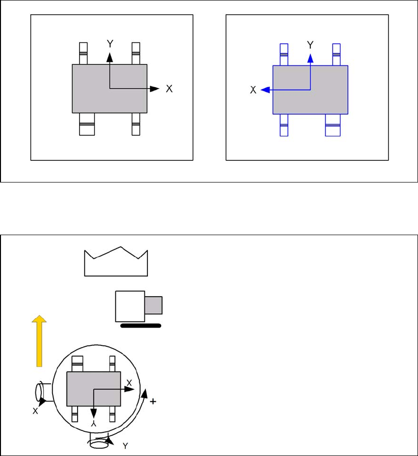
Alignment of the components in the preferred 0° position 12
SST23
0° component position
on the component camera
of the C&P20 head
12
Fig. 12.0 - 2 Alignment of the components in the preferred 0° position - SST 23
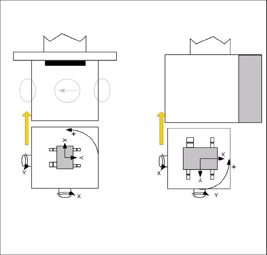
0° component position on
C&P6/12 cameras -
plan view
Direction of rotation of the
star
0° component position
on stationary cameras -
plan view
The gray shading on the camera marks the
illumination part of the 0° plane
SST 28 / SST 29 / SST 30 SST 33 / SST 36 / SST 25
Vision Teach Station User Manual 12 Coordinate systems of the component cameras
10/2015 Edition 11.2 Measuring the component
183
12
Fig. 12.0 - 3 Alignment of the components in the preferred 0° position - SST 28/29/30, SST 33/36/25