00195044-15_UM_VisionTeachStation_DE EN.pdf - 第131页
Vision Teach Station User Manual 5 Installing the cameras 10/2015 Edition 5.2 Installing head cameras, type 28, 29 and 30 131 5 Fig. 5.2 - 10 Base module with camera type 28 Key to fig. 5.2 - 10 , page 131 (1) Magnetic s…
(1)
5
(2)
5
(1)
(3)
0
(4)
5 Installing the cameras Vision Teach Station User Manual
5.2 Installing head cameras, type 28, 29 and 30 10/2015 Edition
130
5
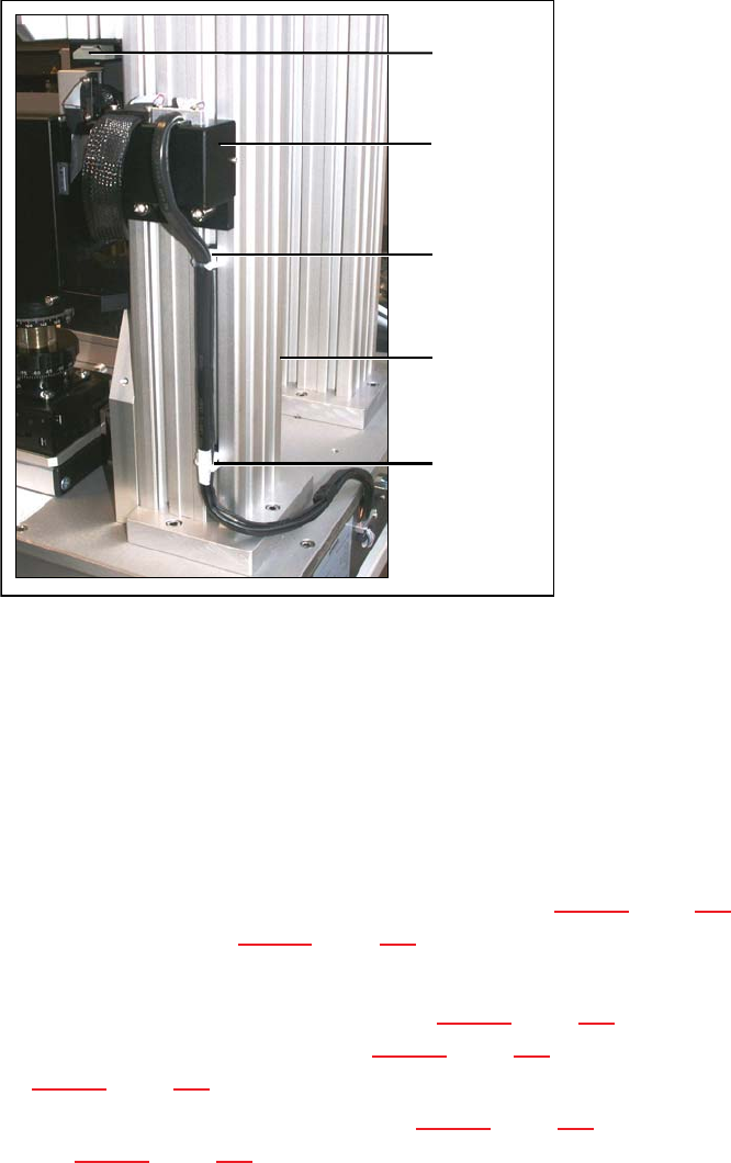
Fig. 5.2 - 9 Running the cables for the camera type SST 28/29 and 23
(1) Wire management mount
(2) Pillar
(3) Wire management mount on camera type 29
(4) Adapter for head camera
5.2.4 Fitting the component support
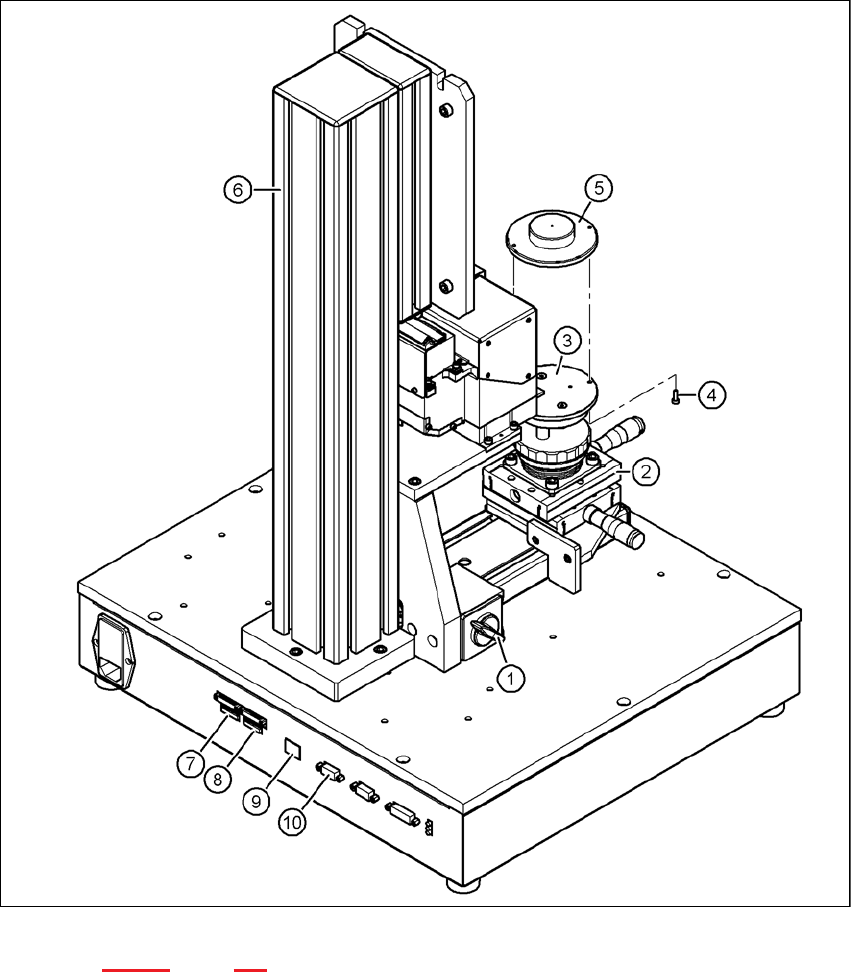
Release the lock on the positioning unit (item 2 in Fig. 5.2 - 10, page 131) using the magnetic
switch (item 1 in Fig. 5.2 - 10, page 131)
Push the positioning unit out.
Fix the component support (item 5 in Fig. 5.2 - 10, page 131) using the two hexagon socket
head screws M3 x 8 (item 4 in Fig. 5.2 - 10, page 131) to the holder (item 3 in Fig.
5.2 - 10, page 131).
Push the positioning unit (item 2 in Fig. 5.2 - 10, page 131) back towards the pillar (item 6 in
Fig. 5.2 - 10, page 131) and lock the positioning unit in place.
Vision Teach Station User Manual 5 Installing the cameras
10/2015 Edition 5.2 Installing head cameras, type 28, 29 and 30
131
5
Fig. 5.2 - 10 Base module with camera type 28
Key to fig. 5.2 - 10, page 131
(1) Magnetic switch
(2) Positioning unit
(3) Holder for component support
(4) Hexagon socket head screw M3 x 8, 2x
(5) Component support, camera type 28/29
(6) Pillar

5 Installing the cameras Vision Teach Station User Manual
5.2 Installing head cameras, type 28, 29 and 30 10/2015 Edition
132
(7) Connection for cable, head camera 1 (03040353-W1: 26-pin, 03040353-W2: 12-pin)
(8) Connection for cable, head camera 2 (03040353-W1: 26-pin, 03040353-W2: 12-pin)
(9) Connection for camera bus cable to the PC (03040359-xx)
(10) Connection for CAN bus cable to the PC (03040362-xx)
5.2.5 Connecting the adapter, base module and PC
Connect the camera bus connection on the base module (item 9 in Fig. 5.2 - 10, page 131) to
the card for the camera bus interface in the PC (item 1 in Fig. 4.3 - 2, page 117) with the cable
03040359-xx.
Connect the CAN bus connection on the base module (item 10 in Fig. 5.2 - 10, page 131) to
the interface card in the PC (item 2 in Fig. 4.3 - 2, page 117) with cable 03040362-xx.