Maintenance Manual.pdf - 第34页
RL131 MAINTENANCE MANUAL 2.3 Maintenanc e Function DA8MEC-10-030- A0 2.3-1 2.3. Maintenance Function DA8MEC-10-030-A0 2.3.1 Introduction Objecti ve The mainten ance switch a llows only the lim ited operati ons to be …
RL131
MAINTENANCE MANUAL
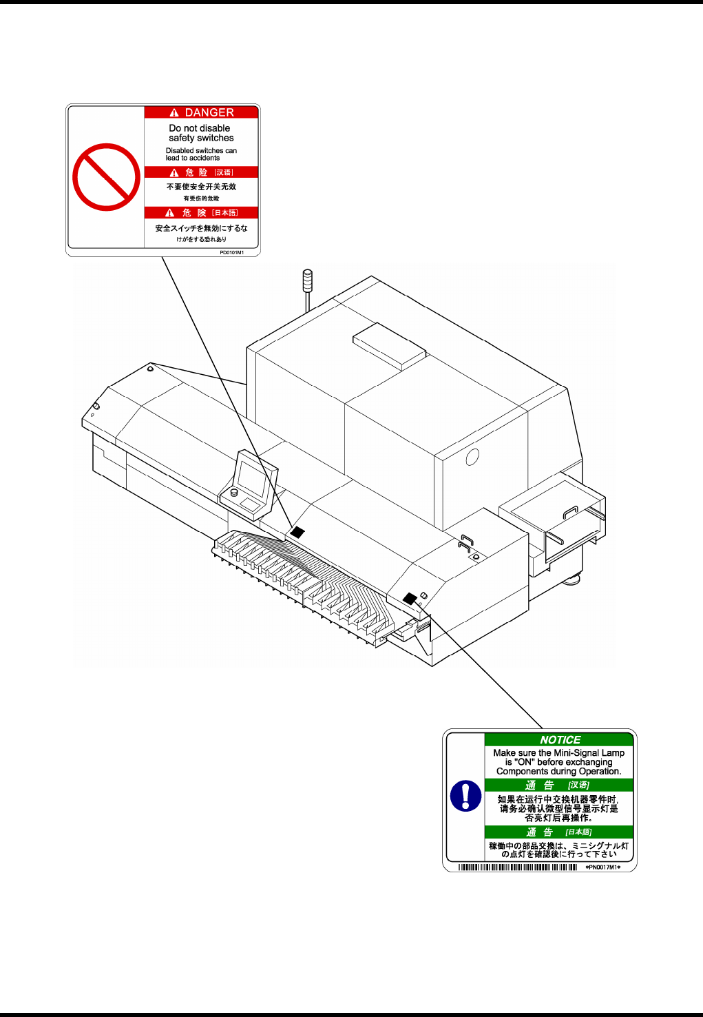
2.2 Locations of Warning Labels
DA8MEC-10-020-A0
2.2-6
Rear-3 (40 inputs)
RL131
MAINTENANCE MANUAL
2.3 Maintenance Function
DA8MEC-10-030-A0
2.3-1
2.3. Maintenance Function
DA8MEC-10-030-A0
2.3.1 Introduction
Objective
The maintenance switch allows only the limited operations to be performed with safety covers open,
thus improving the work efficiency during maintenance.
General Description
The machine is provided with a maintenance switch (key switch); one on the front. This switch is used to
release the safety circuits.
Turning ON the front maintenance switch disables the safety circuits of the transfer rail cover and front
cover.
When the maintenance switch is turned ON, each axis teaching and operations via the sub-control
panel are partly permissible.
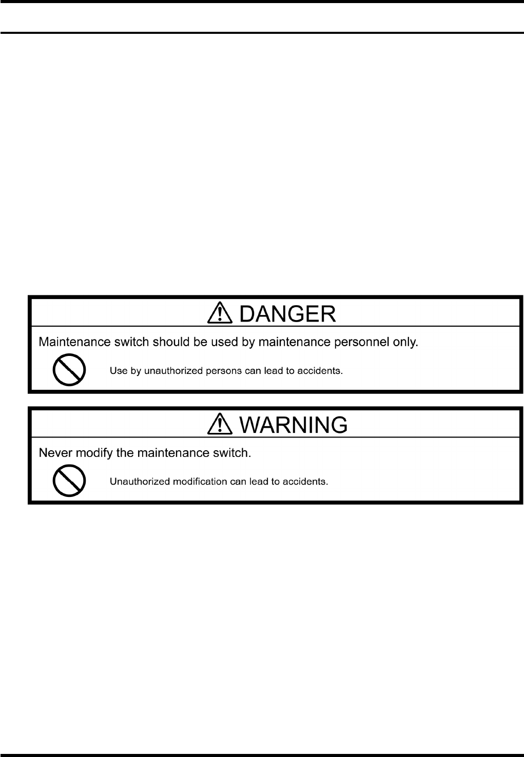
Maintenance mode should be used only when recovering from any troubles which occurred on the
machines. As a rule, only the experienced maintenance engineer who have sufficient knowledge of the
machine are allowed to operate the equipment in this mode.
We shall not be responsible for any accidents caused by the following;
Use of the maintenance switch by workers other than maintenance personnel.
Remodeling the maintenance switch by the user.
RL131
MAINTENANCE MANUAL
2.3 Maintenance Function
DA8MEC-10-030-A0
2.3-2
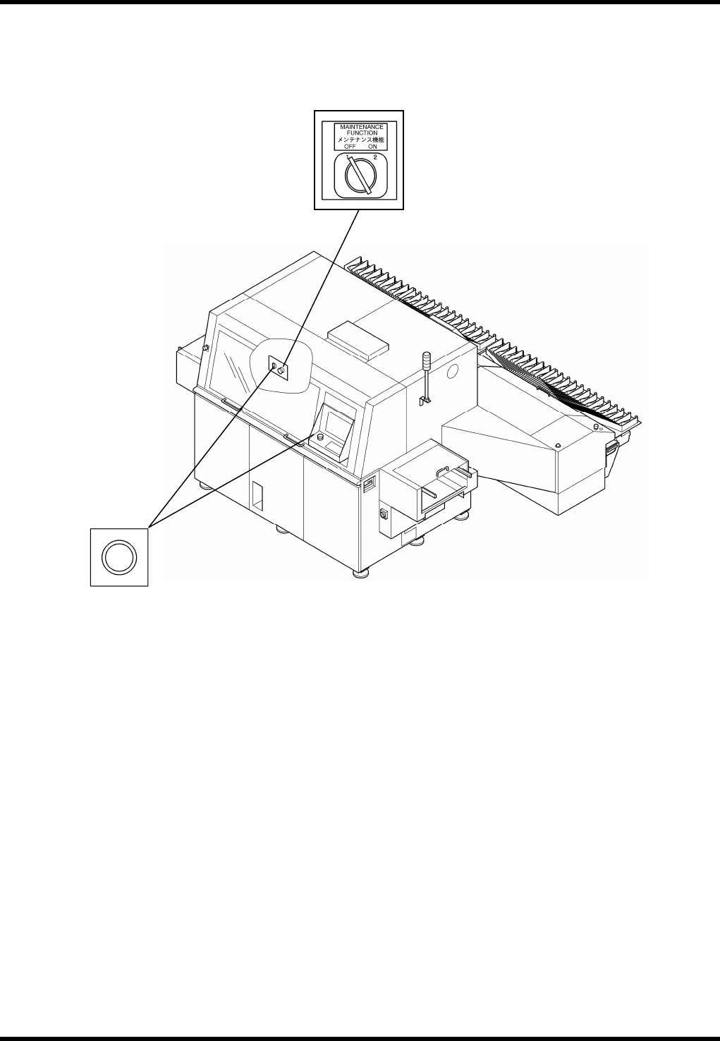
2.3.2 Locations of Switches
Maintenance switch
Enabling switch