Maintenance Manual.pdf - 第73页
RL131 MAINTENANCE MANUAL 4.1 Control S ystem Configu ration DA8MEC-14-020- A0 4.1-4 4.1.4 Driv er MEDDT7364N 01 (For Z, H axes) MCDDT3520N 01 (For Y, C and q H axes ) MBDDT2210N 01 (For X, q A, and P axe s)
RL131
MAINTENANCE MANUAL
4.1 Control System Configuration
DA8MEC-14-020-A0
4.1-3
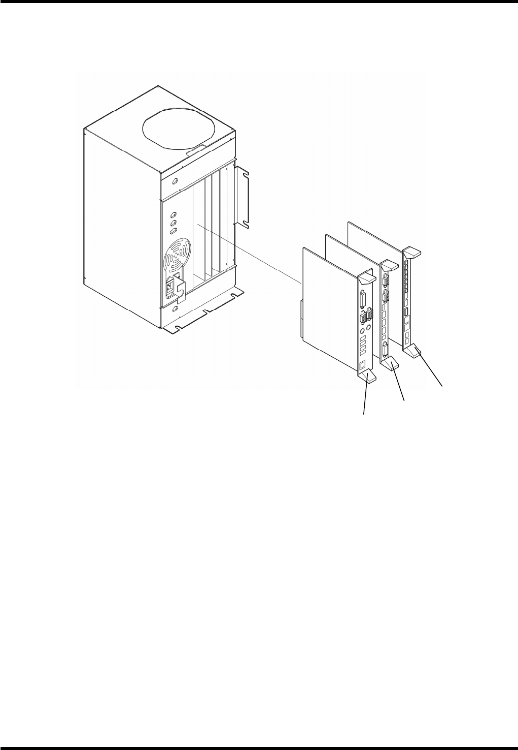
4.1.3 P9
General Description
P9 is a single CPU system controller featuring a 32-bit microcomputer.
Board Configuration
P9 consists of the following boards:
1.
1. PCB-COM board
Model: NBC-JC134X-D
Function: PCB-COM board interfaces with exterior devices.
2. Camera interface board
Model: PPRCAC-AA
Function: The component insertion hole data from the CCD camera is written into the memory and
calculated in comparison to the previously determined standard hole position.
3. Axis and I/O control board
Model: PNFCAA-AA
Function: The board sends signals to AC servo drivers according to values set in the NC program in
order to control AC servomotors.
1.
2.
3.

RL131
MAINTENANCE MANUAL
4.1 Control System Configuration
DA8MEC-14-020-A0
4.1-4
4.1.4 Driver
MEDDT7364N01 (For Z, H axes)
MCDDT3520N01 (For Y, C and qH axes)
MBDDT2210N01 (For X, qA, and P axes)

RL131
MAINTENANCE MANUAL
4.1 Control System Configuration
DA8MEC-14-020-A0
4.1-5
Warning Functions
This motor driver has a function to issue warnings before protective functions are activated, which allows the
user to check for possible abnormal condition such as overload.
When any of the following warnings has occurred, the warning code flashes slowly on the 7-segment LED
on the front panel.
Warning code
No.
Warning Details
16 Overload Load has exceeded 85% of the alarm level.
18 Regenerative overload
Regenerative load has exceeded 85% of the alarm level.
40 Battery
The absolute encoder battery voltage has dropped to approx.
3.2V or below.
88 Locked fan Fan is stopped for more than 1 s.
89 External scale
External scale temperature is 65°C or higher, or signal
strength is insufficient (Adjustment (installation, etc.) is
required.). Available only during full-closed control.
If the overload or regenerative overload warning is detected, take the remedial action in the same way
as when the respective protective functions have occurred.
If the battery warning has occurred, replace the battery for the absolute encoder.
After replacing the battery, clear the alarm of the servo driver once to reset the battery warning.
Protective Functions (Detailed Description of Error Codes)
Function
Error
code No.
Cause Countermeasure
Insufficient
control
voltage
11
Voltage between P and N of the
control power converter dropped to
below the rated value.
1. Low power supply voltage.
Instantaneous power failure
occurred.
2. Insufficient power capacity:
Voltage dropped due to rush
current at power ON.
3. Faulty servo driver (circuit).
Measure the line voltage between the
control power input terminals [connectors
(L1C, L2C) and terminal blocks (r, t)].
1. Increase the power voltage capacity.
Change the power supply.
2. Increase the power capacity.
3. Replace the servo driver.
Overvoltage 12
Voltage between P and N of the
converter exceeded the rated value.
1. The power voltage exceeded the
allowed input voltage range.
Sudden rise in the voltage by the
phase advance capacitor or UPS
(uninterruptible power supply).
2. Regenerative resistor
disconnected.
3. Regenerative energy cannot be
absorbed due to improper external
regenerative resistor.
4. Faulty servo driver (circuit).
Measure the line voltage of the main power
input terminal [connectors (L1, L2, L3)].
1. Input the voltage properly. Remove the
phase advance capacitor.
2. Measure the resistance of the resistor
externally installed between the terminals
P and B of the servo driver using a
tester. If the value is ¥ (infinite), wire is
broken. Replace the external resistor.
3. Change to the specified regenerative
resistance value and wattage.
4. Replace the servo driver.