Maintenance Manual.pdf - 第91页
RL131 MAINTENANCE MANUAL 4.1 Control S ystem Configu ration DA8MEC-14-020- A0 4.1-22 I / O M AP OUTPUT Board connector Address No. Name bit Note 65 P.PUSH (Traverse) valve 0 Option 66 P.PUSH (Return) valve 1 Option 67 2 …
RL131
MAINTENANCE MANUAL
4.1 Control System Configuration
DA8MEC-14-020-A0
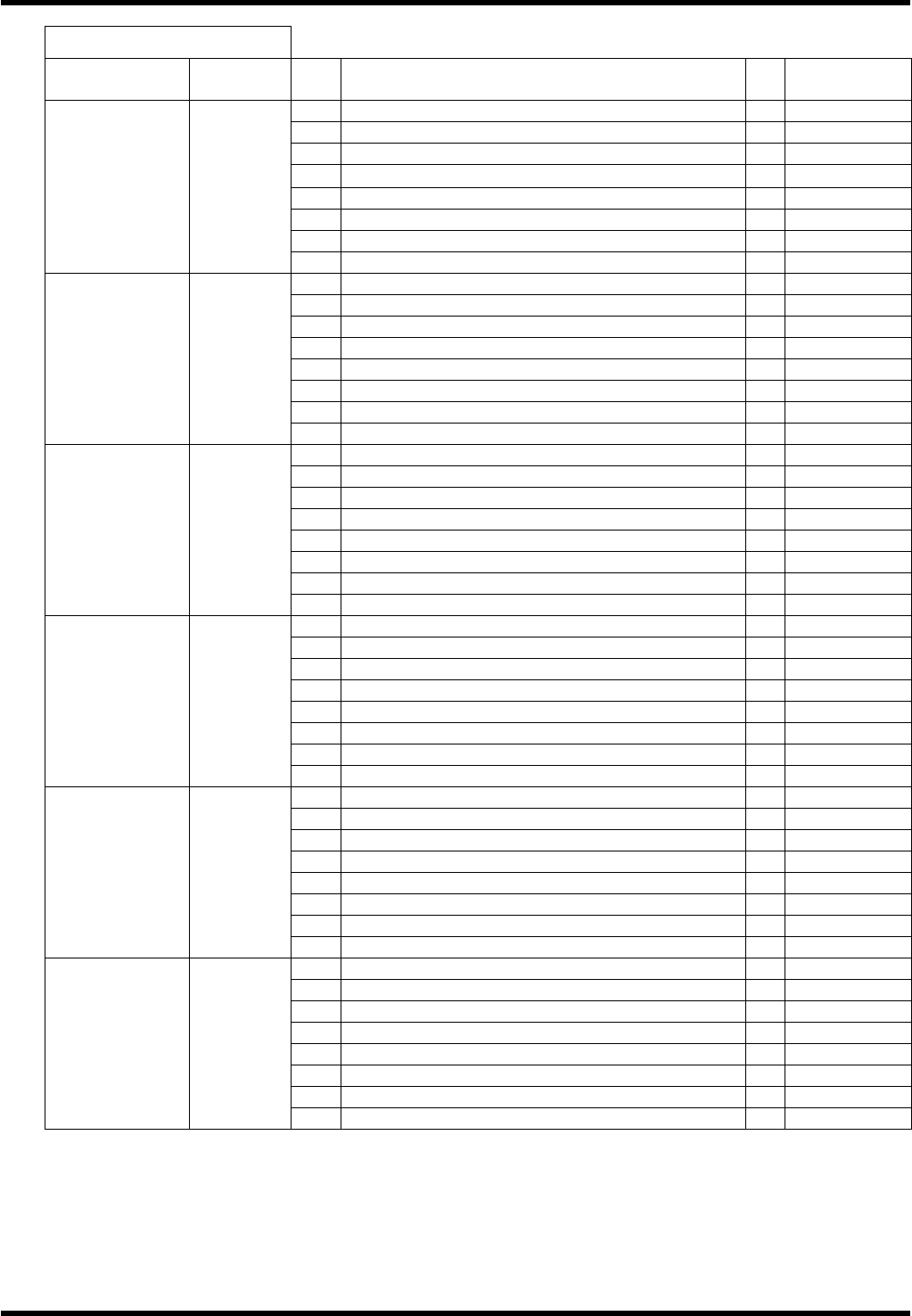
4.1-21
I / O MAP OUTPUT
Board
connector
Address
No.
Name bit
Note
17
Right reference valve 0
Option
18
Reference pin valve 1
Option
19
2
20
3
21
PCB supply valve 4
Option
22
PCB stopper 1 valve 5
Option
23
6
#0_CN9 0022
24
7
25
ZR axis parts changing lamp output 0
26
ZR axis parts changing signal 1
27
ZL axis parts changing lamp output 2
28
ZL axis parts changing signal 3
29
4
30
5
31
6
#0_CN6 0023
32
7
33
Left rail forward valve 0
34
Left rail reverse valve 1
35
Left belt motor right turn 2
36
Left belt motor reverse turn 3
37
Positioner lever valve 4
38
5
39
6
#1_CN5 0060
40
7
41
0
42
Inverter reverse signal 1
43
Inverter speed command 1 2
44
Inverter speed command 2 3
45
Inverter abnormal reset 4
46
Transfer brake release 5
47
Inverter speed command 3 6
#1_CN7 0061
48
7
49
Insertion detection signal output 1 0
50
Insertion detection signal output 2 1
51
Insertion detection signal output 3 2
52
3
53
Insertion detection signal output 4 4
54
Insertion detection signal output 5 5
55
Insertion detection signal output 6 6
#1_CN9 0062
56
7
57
Guide pin select 1 0
58
Guide pin select 2 (2.5) 1
59
Guide pin select 3 (5.0) 2
60
3
61
4
62
5
63
6
#1_CN6 0063
64
7
RL131
MAINTENANCE MANUAL
4.1 Control System Configuration
DA8MEC-14-020-A0
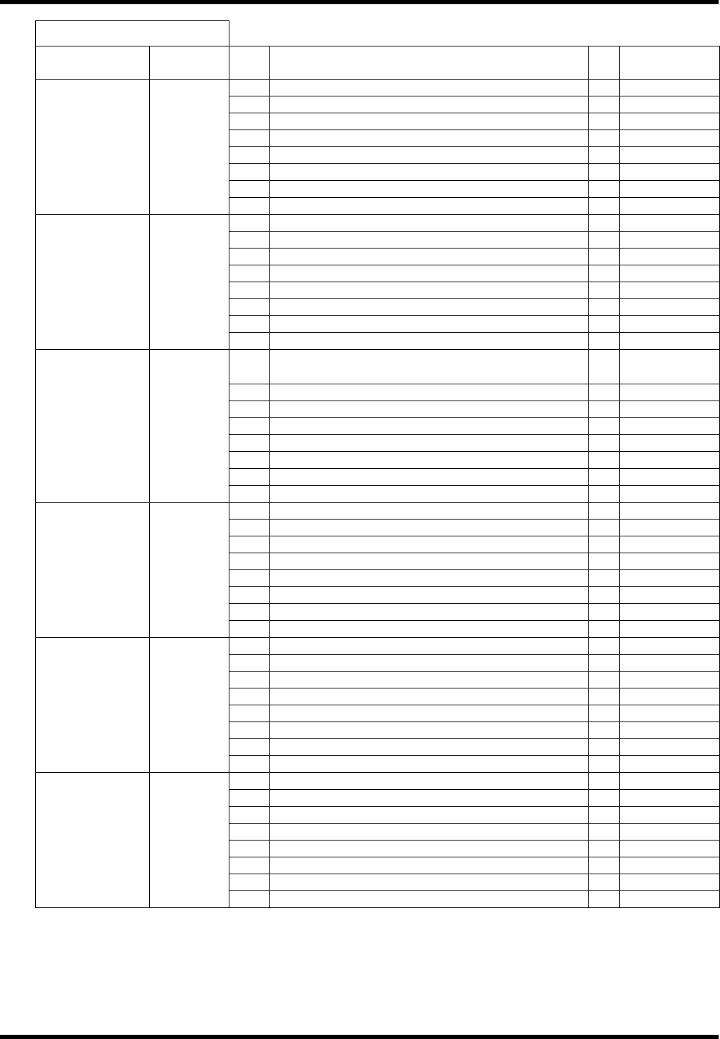
4.1-22
I / O MAP OUTPUT
Board
connector
Address
No.
Name bit
Note
65
P.PUSH (Traverse) valve 0
Option
66
P.PUSH (Return) valve 1
Option
67
2
68
PCB supply valve 3
Option
69
PCB stopper 1 valve 4
Option
70
PCB stopper 2 valve 5
Option
71
6
#1_CN8 0064
72
7
137
Rail open/close valve (BSF-V) 0
Option
138
PCB conveyor motor reverse turn (BSF-V) 1
Option
139
PCB conveyor motor right turn (BSF-V) 2
Option
140
PCB conveyor motor brake (BSF-V) 3
Option
141
Vacuum valve (BSF-V) 4
Option
142
Vacuum suction valve up (BSF-V) 5
Option
143
Vacuum suction valve down (BSF-V) 6
Option
#4_CN5 0120
144
7
145
Automatic width adjustment start signal (SC ®
CONV)
0
Option
146
1
147
2
148
3
149
4
150
5
151
6
#4_CN7 0121
152
7
153
Conveyor belt motor signal 0
Option
154
1
155
2
156
3
157
4
158
5
159
6
#4_CN9 0122
160
7
161
Group empty signal 0
Option
162
Loader empty signal 1
Option
163
Count up signal 2
Option
164
Main body empty signal 3
Option
165
4
166
5
167
6
#4_CN6 0123
168
7
169
L shutter down 0
170
1
171
2
172
3
173
4
174
5
175
6
#12_CN5 0320
176
7
RL131
MAINTENANCE MANUAL
4.1 Control System Configuration
DA8MEC-14-020-A0
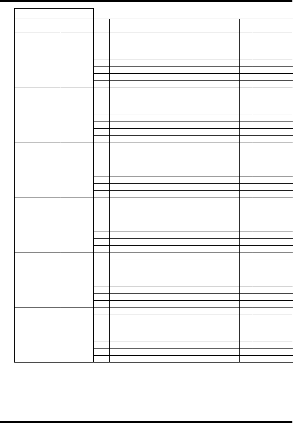
4.1-23
I / O MAP OUTPUT
Board
connector
Address
No.
Name bit
Note
177
R shutter down 0
178
1
179
2
180
3
181
4
182
5
183
6
#12_CN7 0321
184
7
185
L feeder forward 0
186
1
187
2
188
3
189
4
190
5
191
6
#12_CN9 0322
192
7
193
R feeder forward 0
194
1
195
2
196
3
197
4
198
5
199
6
#12_CN6 0323
200
7
201
Force oiling 0
202
Positional correction pallet open lock 1
203
Positional correction 2.5 mm 2
204
Positional correction 7.5mm 3
205
4
206
V cut position down 5
207
Part correction cancel cylinder 6
#12_CN8 0324
208
7
209
Signal tower (Red / Yellow) 0
210
Signal tower (Yellow / White) 1
211
Signal tower (Green) 2
212
Buzzer output 3
213
Origin display LED 4
214
5
215
6
#13_CN5 0360
216
7
217
0
218
1
219
2
220
3
221
Insertion chuck open 4
222
Guide chuck open 5
223
Insertion chuck close 6
#13_CN7 0361
224
Guide chuck close 7