Maintenance Manual.pdf - 第83页
RL131 MAINTENANCE MANUAL 4.1 Control S ystem Configu ration DA8MEC-14-020- A0 4.1-14 I / O M AP INPUT Board connector Address No. Name bit Note 217 L feeder norm al position 0 218 L feeder standb y position 1 219 Feeder …
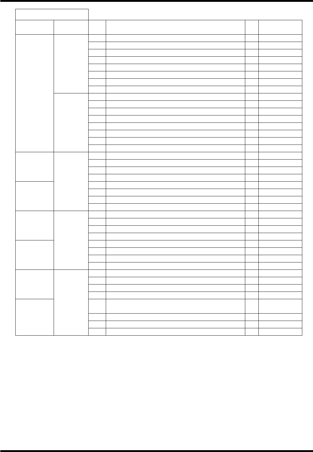
RL131
MAINTENANCE MANUAL
4.1 Control System Configuration
DA8MEC-14-020-A0
4.1-13
I / O MAP INPUT
Board
connector
Address
No.
Name bit
Note
177
Vacuum upper limit (BSF-V) 0
Option
178
Vacuum lower limit (BSF-V) 1
Option
179
PCB vacuum detection (BSF-V) 2
Option
180
PCB carry traverse limit (BSF-V) 3
Option
181
PCB carry return limit (BSF-V) 4
Option
182
No-PCB detection (BSF-V) 5
Option
183
Safety cover SW (BSF-V) 6
Option
0103
184
VACUUM SW (BSF-V) 7
Option
185
UP SW (BSF-V) 0
Option
186
DOWN SW (BSF-V) 1
Option
187
Rail open/close SW (BSF-V) 2
Option
188
FOWARD SW (BSF-V) 3
Option
189
REVERSE SW (BSF-V) 4
Option
190
5
191
6
#4_CN10
0104
192
7
193
L shutter lower left limit 0
194
L shutter lower right limit 1
195
L shutter upper left limit 2
#12_CN16
196
L shutter upper right limit 3
197
R shutter lower left limit 4
198
R shutter lower right limit 5
199
R shutter upper left limit 6
#12_CN15
0300
200
R shutter upper right limit 7
201
V cutter return detection 0
202
Tape detection after V-cut 1
203
Pallet chuck lock close detection 2
#12_CN14
204
3
205
Pallet part position check 1 4
206
Pallet part position check 2 5
207
Pallet part detection 6
#12_CN13
0301
208
Pallet part remain detection 7
209
C AXIS ORG 0
210
1
211
2
#12_CN12
212
3
213
Cover open/close safety SW (Part processing
unit)
4
214
Cover open/close safety SW (Pulley) 5
215
6
#12_CN11
0302
216
7
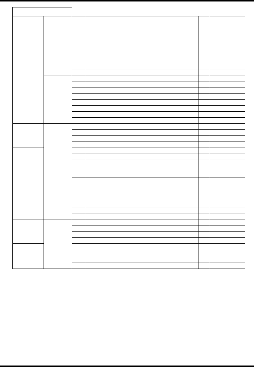
RL131
MAINTENANCE MANUAL
4.1 Control System Configuration
DA8MEC-14-020-A0
4.1-14
I / O MAP INPUT
Board
connector
Address
No.
Name bit
Note
217
L feeder normal position 0
218
L feeder standby position 1
219
Feeder L feed check 1 2
220
Feeder L feed check 2 3
221
Feeder L installation check 4
222
5
223
6
0303
224
7
225
R feeder normal position 0
226
R feeder standby position 1
227
Feeder R feed check 1 2
228
Feeder R feed check 2 3
229
Feeder R installation check 4
230
5
231
6
#12_CN10
0304
232
7
233
Transfer oscillation forward 0
234
Transfer head traverse/return lock 1
235
Transfer pallet close lock 2
#13_CN16
236
3
237
Upper frame right fan 4
238
C axis side fan 5
239
Upper frame left fan 6
#13_CN15
0340
240
7
241
qU axis A side position
0
242
qU axis B side position
1
243
Transfer forward/backward return detection 2
#13_CN14
244
3
245
4
246
5
247
6
#13_CN13
0341
248
P AXIS ORG. 7
249
Z AXIS ORG 0
250
1
251
2
#13_CN12
252
3
253
qH AXIS +LIMIT
4
254
qH AXIS ORG.
5
255
qH AXIS –LIMIT
6
#13_CN11
0342
256
7

RL131
MAINTENANCE MANUAL
4.1 Control System Configuration
DA8MEC-14-020-A0
4.1-15
I / O MAP INPUT
Board
connector
Address
No.
Name bit
Note
257
System reserve 0
258
System reserve 1
259
Handle detection 2
260
3
261
4
262
5
263
6
0343
264
7
265
Bad mark detection 0
Option
266
1
267
2
268
3
269
4
270
5
271
6
#13_CN10
0344
272
7
273
Part presence 1 0
274
Part presence 2 1
275
Part presence 3 2
#14_CN16
276
Part presence 4 3
277
Part presence 5 4
278
Part presence 6 5
279
Part presence 7 6
#14_CN15
0380
280
Part presence 8 7
281
Part presence 9 0
282
Part presence 10 1
283
Part presence 11 2
#14_CN14
284
Part presence 12 3
285
Part presence 13 4
286
Part presence 14 5
287
Part presence 15 6
#14_CN13
0381
288
Part presence 16 7
289
Part presence 17 0
290
Part presence 18 1
291
Part presence 19 2
#14_CN12
292
Part presence 20 3
293
Part presence 21 4
294
Part presence 22 5
295
Part presence 23 6
#14_CN11
0382
296
Part presence 24 7