YS24_Mainte_E.pdf - 第103页
3-39 3 Periodic maintenance items 4.7 Inspecting and replacing the air and oil mist filter T he air filter and oil mist filter are used in this unit to prevent oil, water , impure objects in the air compressor from enter…
3-38
3
Periodic maintenance items
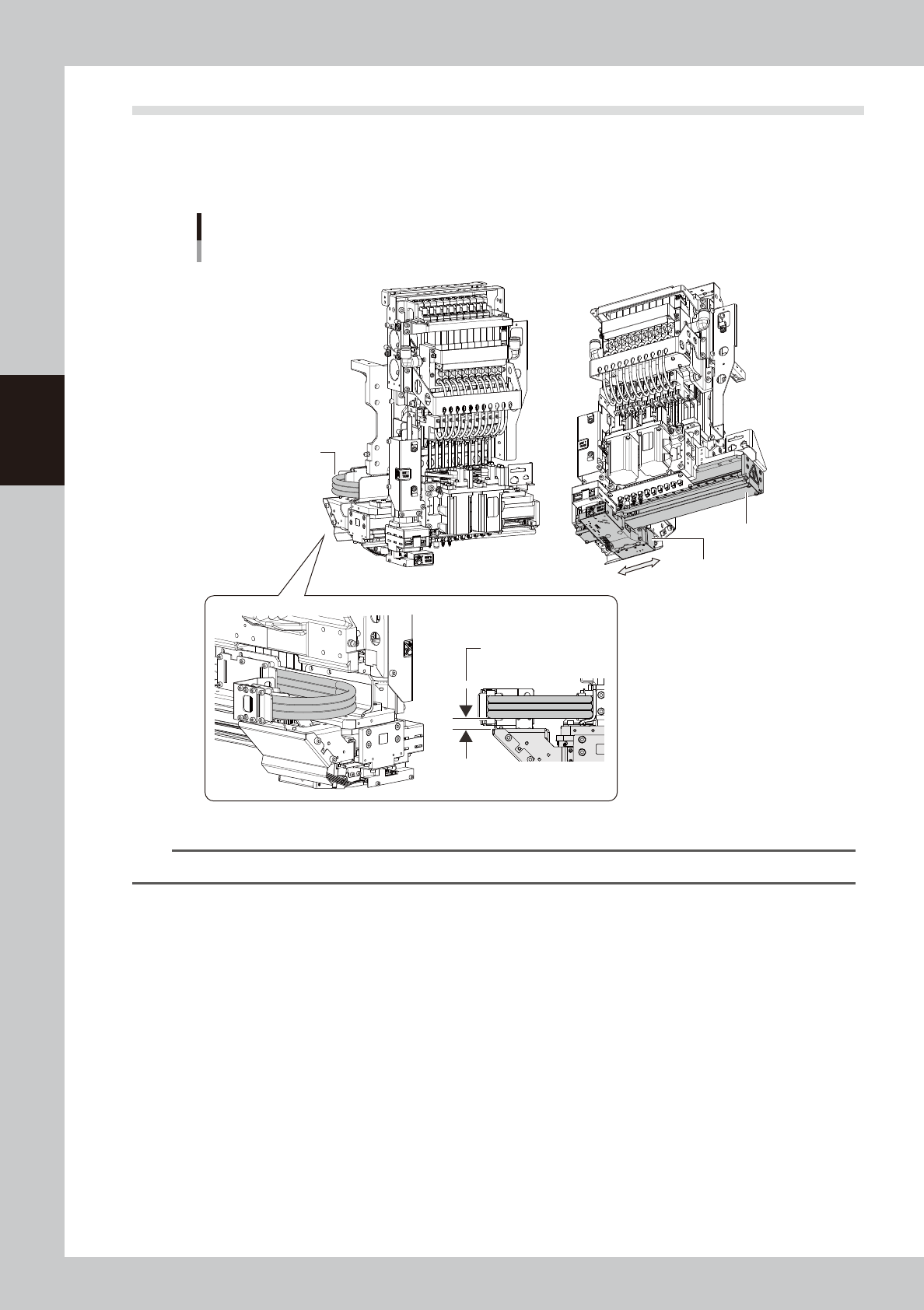
4.6 Checking the SC-axis flex cable
The SC-axis flex cable is a flat multi-cable designed for rigidity to prevent the harness from drooping as it
moves along with the scan camera. However, the cable may eventually droop due to warping or weakening
from long-term use. If cable drooping occurs, then the cable may come in contact with moving parts and cause
trouble. We recommend making periodic checks and replacing the cable if drooping becomes obvious.
SC-axis unit
Checking the SC-axis flex cable condition
Scan camera
Check for drooping
in the flex cable.
Head assembly
No drooping allowed
in the flex cable.
53351-L2-10
n
NOTE
If drooping in the SC-axis flex cable becomes obvious, contact YAMAHA sales representative.
3-39
3
Periodic maintenance items
4.7 Inspecting and replacing the air and oil mist filter
The air filter and oil mist filter are used in this unit to prevent oil, water, impure objects in the air compressor
from entering into the machine. In this section, inspection and cleaning of these filters, and replacing method
of the inside filter element are shown below. In order to perform this work safely, always remove the air
coupler at the air supply connection unit.
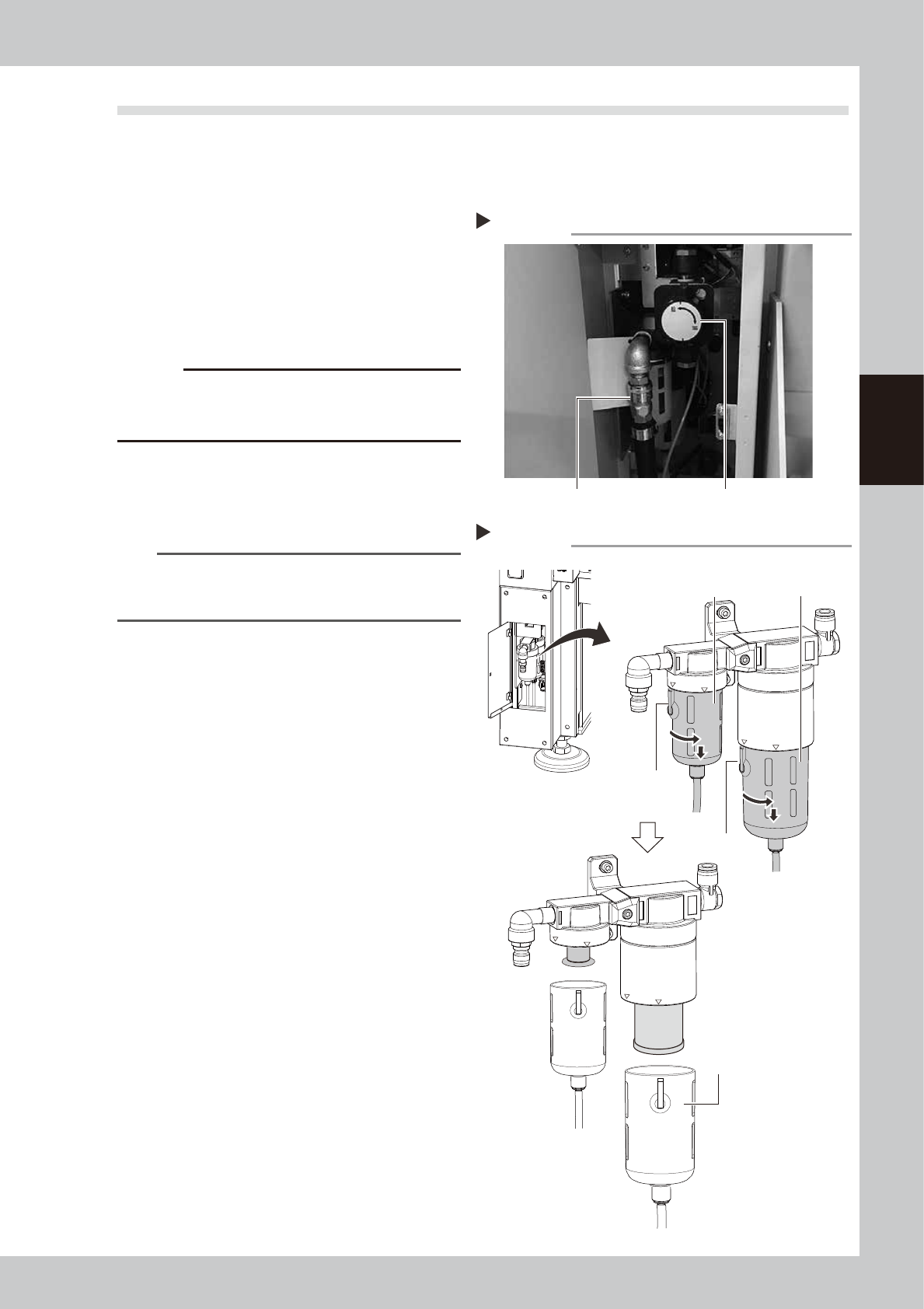
1
Remove the air coupler of air
supply.
1. Turn the air supply/exhaust switch
clockwise to turn air supply OFF.
2. Remove the air coupler on the air supply
connection unit.
53363-L2-10
c
CAUTION
Be aware that a loud air exhaust sound is heard when
disconnecting the air coupler. Use care to prevent oil,
water, and impurities, etc., from being sprayed out.
2
Check the inside of the filer cup.
Check if oil or water is in the cup. When oil
or water is dirty, clean it by following Step 3
to 4.
TIP
The drain valve at the bottom of cup is an auto-drain
type. When oil and water fills the cup, it is automatically
discharged.
3
Remove the cup.
1. While pressing the button on the filter
cup, turn the cup clockwise.
2. Match the button to the “IN” display
location on the filter housing, and pull
down the cup to remove.
53325-L2-10
Step 1
Removing the air coupler
Air coupler Air supply/exhaust switch
Removing the filter cup
Step 3
Oil mist filter
Button
LOCK
IN
LOCK
IN
Button
Air filter
Filter cup
3-40
3
Periodic maintenance items
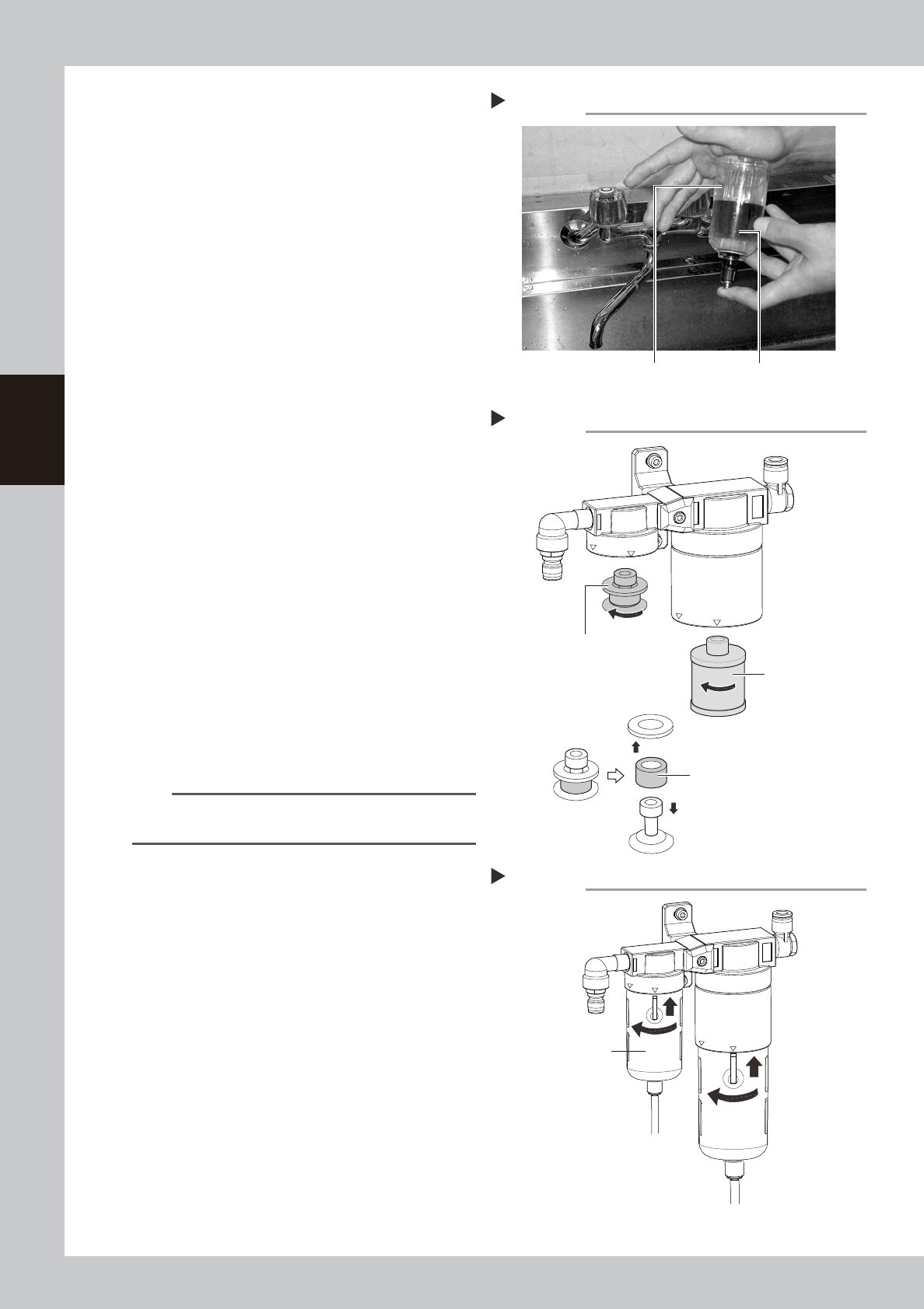
4
Clean the inside of the filter cup.
1. Lightly clean the filter cup with water.
2. Pour water-diluted neutral detergent into
the filter cup and clean the inside.
3. After blowing air to the filter cup, wipe
away any moisture with cloth.
53326-L2-00
5
Remove the filter element.
Air filter:
Turn the element ASSY counterclockwise
to remove.
The filter element is set between the top
and bottom adapters.
Oil mist filter:
Turn the filter element counterclockwise
to remove.
53365-L2-00
6
Check the state of element.
Check there is no dirt and clogging in the
filter element. If dirt and clogging are found,
replace with a new filter element.
7
Attach the filter element.
Follow the reverse order of removing the
element to remove the filter element.
8
Attach the cup.
1. Match the cup’s button to the displayed
location of “IN” on the filter housing, and
push the cup up.
2. Turn the cup counterclockwise to the
displayed location of “LOCK”.
53393-L2-00
TIP
You hear a click sound when the cut is set on the
“LOCK” location properly.
9
Reconnect the air coupler.
1. After reconnecting the air coupler, check
that no air is leaking.
2. Turn the air supply/exhaust switch
counterclockwise to restart air supply.
Cleaning the filter cup
Step 4
Filter cup
Water-diluted
neutral detergent
Removing the filter element
Step 5
Mist filter element
(Air) filter element
Filter element ASSY
Lock
IN
Lock
IN
Step 8
Reattaching the filter cup
Filter cup