YS24_Mainte_E.pdf - 第109页
3-45 3 Periodic maintenance items 5.2 Cleaning the scan camera T he light diffuser plate and prism of the scan camera may become dirty . P eriodic cleaning is recommended. c CAUTION Do not apply strong for ce to the came…
3-44
3
Periodic maintenance items
5. Six-month inspection
5.1 Cleaning the fiducial camera
The fiducial camera is mounted on the right side of the head unit (the left side camera is optional). Dust may
be attached to the lighting unit of this camera, and therefore, it is recommended to perform periodical
cleaning.
c
CAUTION
Do not apply strong force or shock to the camera unit and lighting unit during cleaning. Optical axis adjustment might
become unreliable.
c
CAUTION
If trouble occurs with the lighting unit, then contact YAMAHA sales representative. Disassembly and cleaning of the
lighting unit by the user will void the warranty.
1
Move the head unit.
e
1. Remove everything affected by
magnetism such as wrist watches,
magnetic ID card, etc.
2. Press the emergency stop button and
then open the machine safety cover.
3. If the machine is equipped with a
carriage, remove the carriage to allow
you to easily access the head unit.
4. Move the head unit to make cleaning
easy.
2
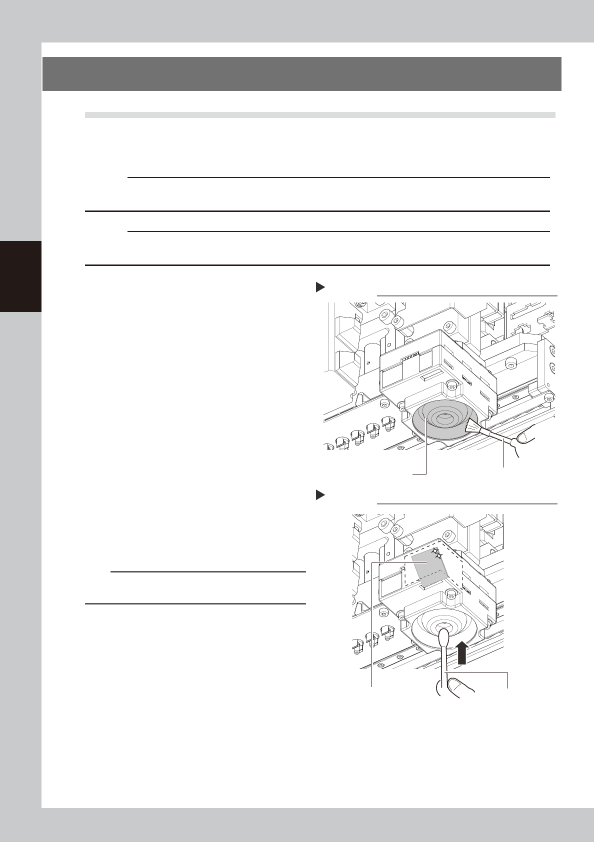
Clean the lighting unit.
Remove dust on the lighting unit with the
blower brush.
533F3-L2-00
3
Clean the diffuser plate.
Put a few drops of lens cleaner on a cotton
swab, and clean the diffuser plate unit as
shown in the right figure.
533F4-L2-00
TIP
The blower brush and lens cleaner must be purchased
as option.
Lighting unit for fiducial mark camera
Remove dust with the blower brush.
Step 2
Blower brush
The cotton swab
with lens cleaner
Cleaning the diffuser plate.
Step 3
Diffuser plate
3-45
3
Periodic maintenance items
5.2 Cleaning the scan camera
The light diffuser plate and prism of the scan camera may become dirty. Periodic cleaning is recommended.
c
CAUTION
Do not apply strong force to the camera parts during cleaning. Doing so may damage the glass components used in
the camera unit.
1
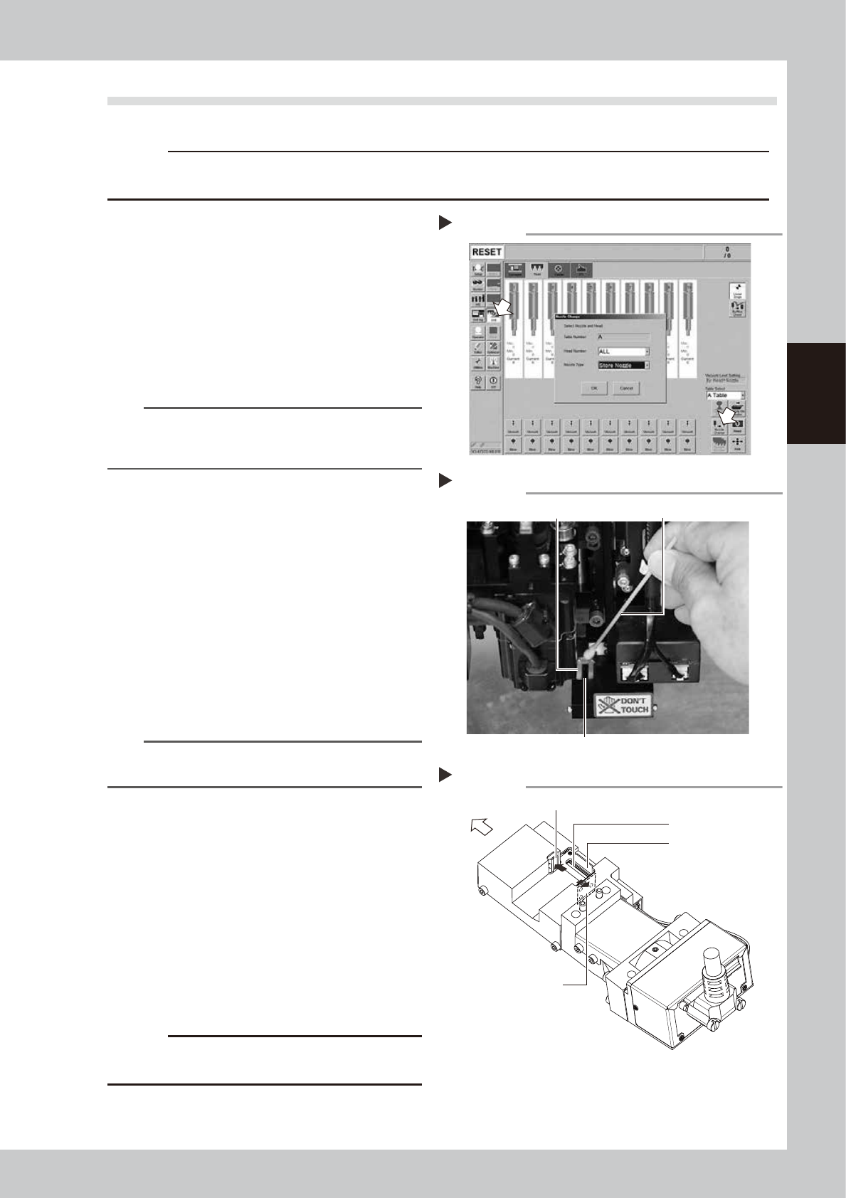
Remove the nozzles from all heads.
If nozzle station is equipped with the machine:
1. Press the [Nozzle Change] button on the
[Unit] - [Head] screen.
2. Select "ALL" for the Head Number and
select "Store Nozzle" for Nozzle type on
the "Nozzle Change" screen.
3. Press the [OK] button. The nozzles of all
heads are stored to the nozzle station.
54312-L2-10
n
NOTE
If the machine is not equipped with the nozzle station,
press the emergency stop button and then open the
machine safety cover to remove nozzles manually.
2
Move the head unit forward.
e
1. Remove everything affected by
magnetism such as wrist watches,
magnetic ID card, etc.
2. Press the emergency stop button to open
the machine safety cover.
3. Move the head unit forward.
3
Move the scan camera.
1. Move all heads (nozzle holder sections)
manually to their upper ends.
2.
Move the scan camera to the right side of
the R-axis motor. At this point, do not
apply excessive force to the scan camera.
n
NOTE
When the machine has only one fiducial camera, moving
the scan camera to the left end will make cleaning easier
.
4
Wipe the diffuser plate and prism.
1.
Use a cotton swab to remove dust and
dirt on the upper surface of the main light
diffuser plate and on the prism surface. As
the prism surface is narrow, twist the end
of the cotton swab into a pointed tip and
use it to wipe the prism surface lightly.
2.
Wipe the side-view light diffuser plate and
prism with a cotton swab. Use a hand
mirror when wiping the prism surface as it
cannot be seen from the front.
53360-L2-00
53361-L2-00
c
CAUTION
Do not use solvent. It may cause the surface finish of the
prism to peel or flake and the diffuser plate to discolor.
5
Return the nozzles.
Return the nozzle to its original head if nozzle
was removed manually.
Cleaning the light diffuser plate and prism
Step 4
Light diffuser plate
Prism
Cotton swab
Cleaning points of light diffuser plate and prism
Main diffuser plate
Side-view diffuser plate
Side-view prism
Front of machine
Main prism
Step 4
Returning all nozzles to nozzle station.
Step 1
3-46
3
Periodic maintenance items
5.3 Cleaning and lubricating the W-axis
Every six months, cleaning and lubrication of the ball screw, guide, and hex spline of W axis are necessary. For
lubrication locations, see "Chapter 5 Lubrication points and schedule". For lubrication of the dual stage W2
axis (U axis), see "4.8 Dual stage only: Cleaning and lubrication of U axis (W2 axis)" in this chapter.
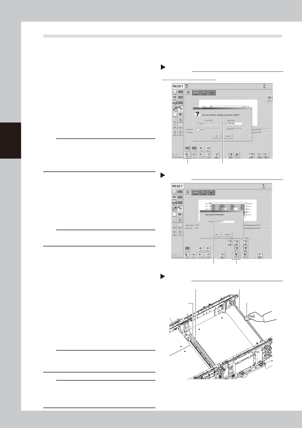
1
Change the conveyor width to its
maximum width.
1. Press the [Conveyor Width] button on the
[Unit] – [Conveyor] screen to display the
“Conveyor Width” screen.
2. Enter the maximum value of the
conveyor width in the “Changed
conveyor width”, press [OK]. The
conveyor is changed to the width that
was just entered.
54318-L2-00
TIP
The maximum value of the conveyor width is 460 mm
for the single lane and dual stage specifications. In
case of the dual lane specification, the maximum value
of the conveyor width in one side lane is 382 mm. Enter
382 mm on lane 1.
2
(For dual stage specification only)
Move the stage 2 up.
1. Push the [Stage 2] - [Pushup] button to
display the “Conveyor Pushup” screen.
2. Enter “0.1 mm” in Thickness, and press
the [OK] button. The stage 2 moves up.
54317-L2-00
n
NOTE
By moving up the stage 2, it becomes easier to access
the W3-axis ball screw and guide.
e
3
Clean the each part of W-axis.
1. Press the emergency stop button, and
open the machine’s safety cover.
2. If the machine is equipped with a
carriage, remove to the carriage for
easy access to the w-axis.
3. Remove everything affected by
magnetism such as wrist watches,
magnetic ID card, etc.
4. Wipe the old grease and soiling from the
W-axis ball screw, guide, and the whole
hexagon spline with a lint-free cloth that
does not raise dust.
53368-L2-00
n
NOTE
When performing cleaning, clean the lead groove part
of the ball screw and the groove of the guide rail
carefully. Also, make sure no dust is generated.
n
NOTE
The number of cleaning areas (ball screw, guide, and
hex spline) differs depending on the specification of
the machine. See "Chapter 5 Lubrication points and
schedule".
Changing the conveyor width
Step 1
[width] button Enter the maximum conveyor value
Dual lane specification screen
Enter the pushup board thickness
Step 2
[Push Up] buttonEnter the thickness
Cleaning the each part of W-axis
Step 3
Guide
Lint-free cloth
Hexagon spline
Ball screw