YS24_Mainte_E.pdf - 第69页
3-5 3 Periodic maintenance items 5 Clean the nozzle tip. Push the nozzle tip vertically against the adhesive sur face of the nozzle tip cleaning tape several times to remove dirt. 53320-L2-00 c CAUTION If turning or tilt…
3-4
3
Periodic maintenance items
1.2.2 Cleaning the nozzle tip
A little dirt at the nozzle tip can be cleaned with the "Nozzle tip cleaning tape" that comes with the machine.
If cleaning the nozzle with an ultrasonic cleaner (option) and then cleaning with the nozzle tip cleaning tape,
the nozzle tip can be cleaned effectively.
The following describes the cleaning procedure of the spring-action nozzle tip with an ultrasonic cleaner and
the nozzle tip cleaning tape.
c
CAUTION
When cleaning the nozzle tip, use YAMAHA recommended cleaning tape (TAPE,CLEANER:KGT-M8895-00X) only. If
using other tape, the adhesive surface may adhere to the nozzle and may cause the mounting failure.
n
NOTE
See the Service Information that comes with the tape for how to use the cleaning tape.
e
1
Remove nozzles.
1. Press the emergency stop button and
then open the machine safety cover.
2. Remove nozzles from the head. If the
machine is equipped with the nozzle
station, press the [Nozzle Stn Shutter]
button to open the nozzle station shutter
and remove nozzles.
2
Clean the slide section.
If dust is found in the slide section, remove it
with an air blow tool (option), etc.
53306-L2-00
3
Clean nozzles with an ultrasonic
cleaner.
1. Put nozzles into a container (such as
beaker) in an ultrasonic cleaner.
2. Pour IPA in a container until nozzles are
dipped.
3. Pour water in an ultrasonic cleaner.
4. Clean nozzles with an ultrasonic cleaner
for about 10 minutes.
53309-L2-00
n
NOTE
When cleaning a nozzle with an O-ring such as Type
304A or Type 307A nozzle using an ultrasonic cleaner,
remove an O-ring and clean a nozzle itself only.
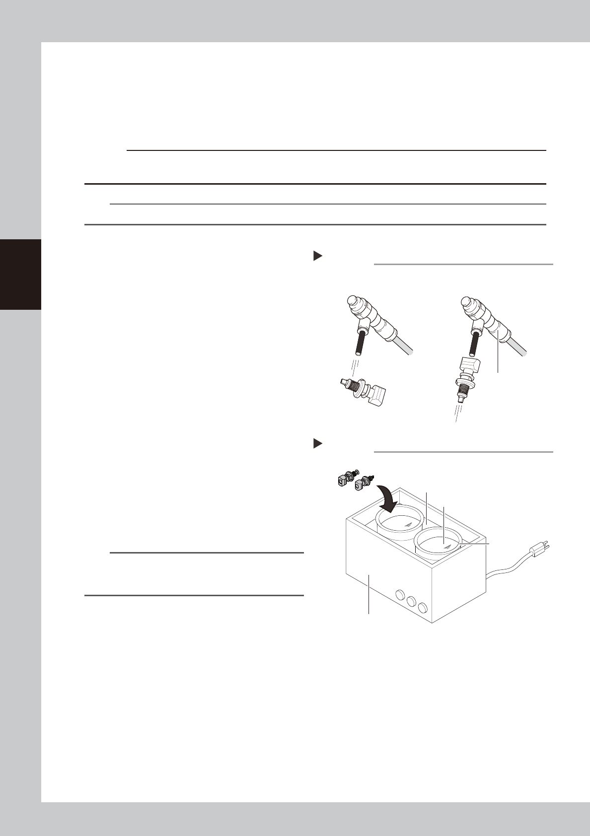
4
Blow nozzles.
1.
Take nozzles out from an ultrasonic cleaner
.
2. Blow entire nozzle to remove IPA.
Intensively blow the slide section and the
air path.
Air blow
Step 2, 4
Air blow tool (option)
■ Blowing air path
■ Blowing slide section
Ultrasonic cleaner
Step3
Ultrasonic cleaner
Beaker
Pour water.
Pour IPA.
3-5
3
Periodic maintenance items
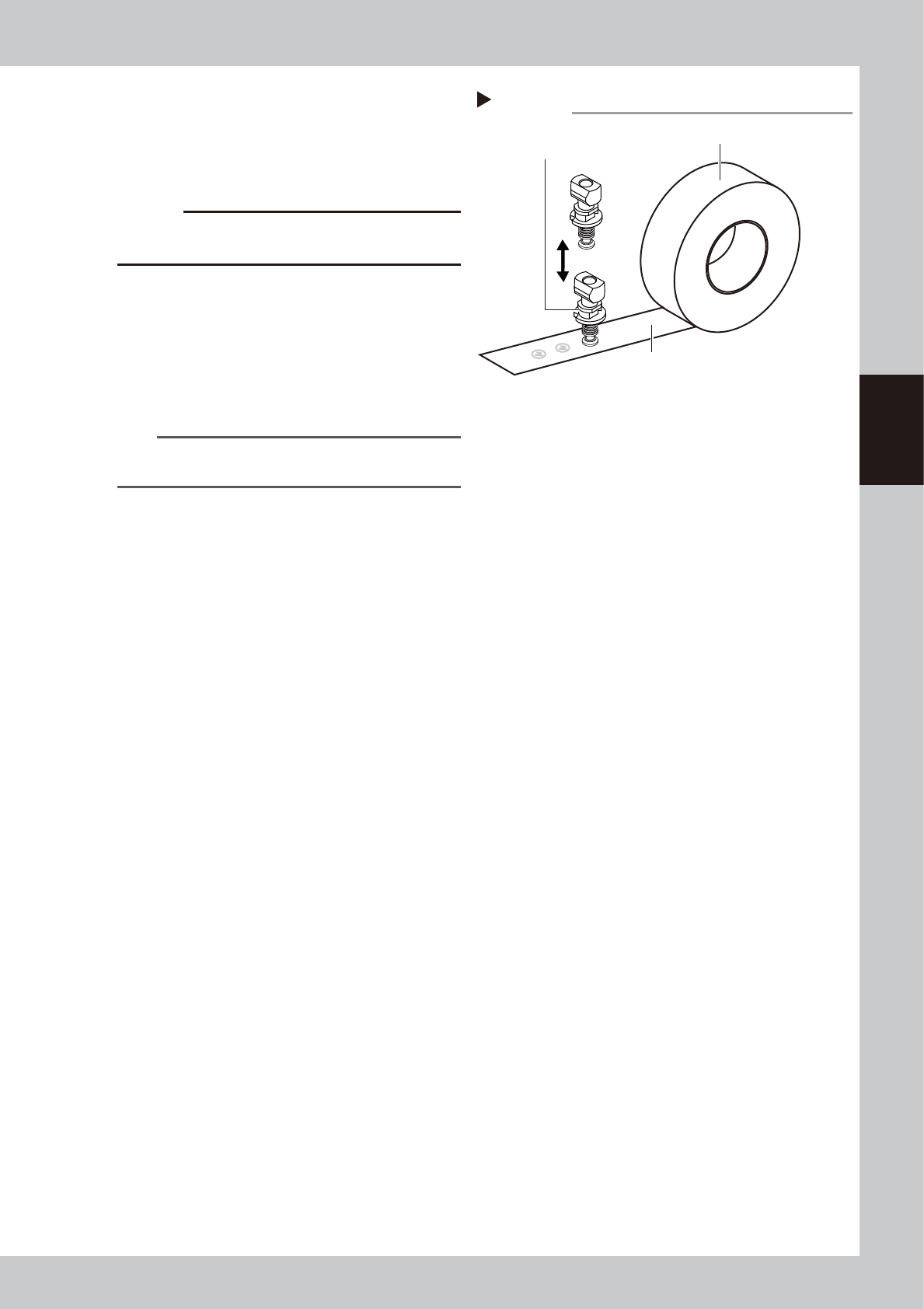
5
Clean the nozzle tip.
Push the nozzle tip vertically against the
adhesive surface of the nozzle tip cleaning
tape several times to remove dirt.
53320-L2-00
c
CAUTION
If turning or tilting a nozzle while pushing it against the
tape, the adhesive surface may stick to the nozzle.
6
Lubricate the slide section.
See "1.2.1 Cleaning and lubricating the
nozzle buffing area" in this chapter to
lubricate the nozzle buffing area.
7
Return nozzles to the head.
Return the removed nozzles to the head.
n
NOTE
If removed nozzles from the nozzle station, return them
to the nozzle storage positions.
Nozzle tip cleaning tape
Step 5
Nozzle tip cleaning tape
Adhesive surface
Push nozzle vertically.
3-6
3
Periodic maintenance items
1.3 Checking the conveyor sensor condition and operation
This machine uses a transmission type fiber sensor as the conveyor sensor.
As the conveyor width changes, the distance between the light emitting and light receiving sensors also
changes. Accordingly, the light receiving status of the sensor may change.
Therefore, a conveyor sensor tuning function is provided on this machine that stores the sensor light receiving
status after the conveyor rail width has been changed and automatically rewrites the sensor threshold value.
By changing the conveyor rail width periodically, you can check that the conveyor sensors and conveyor sensor
tuning operate correctly.
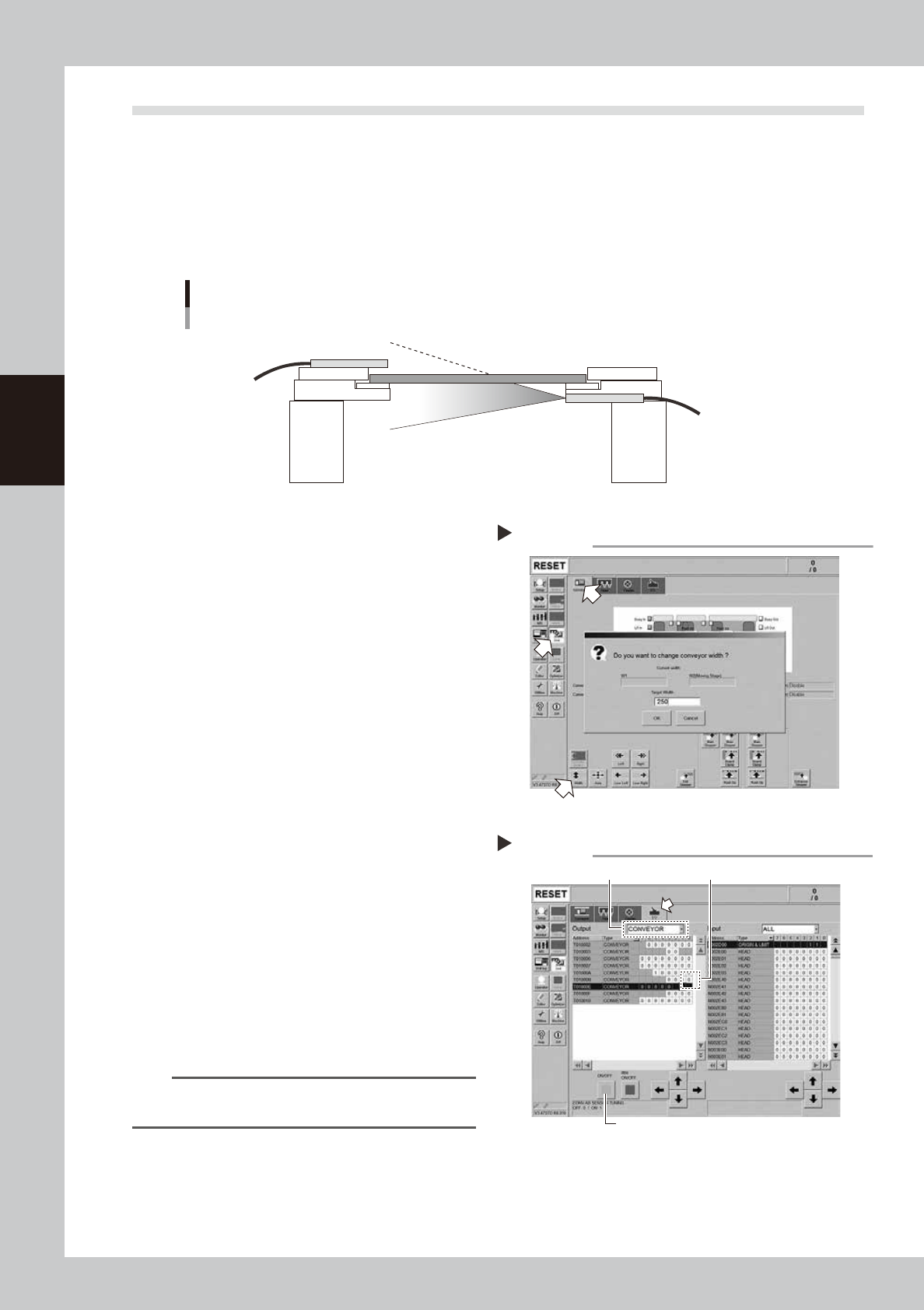
Checking the conveyor sensor condition and operation
Light emitting
Light receiving
53353-L2-10
1
Open the [Unit] – [Conveyor]
screen.
2
Press the [Width] button to change
the conveyor width.
In the "Conveyor Width" screen that
appears, enter a conveyor width and press
[OK] button.
The conveyor is changed to the width that
was just entered.
3
Check whether an error has
occurred.
The conveyor sensor is operating properly
unless an error message appears when the
conveyor width is changed. No further
check is necessary.
If an error occurred, perform "Conveyor
sensor tuning" from Step 4.
54301-L2-10
4
Perform the conveyor sensor
tuning.
1. Open the [Unit] – [I/O] screen.
2. From the "Output" drop-down list, select
"CONVEYOR".
3. Select "CONV SENSOR TUNING" (T01000E1)
in the output I/O list.
n
NOTE
In dual-lane machines, "T01000E1" corresponds to Lane
1, and "T01000E3" to Lane 2.
4. Press the [ON/OFF] button to switch the I/
O status from "0" (OFF)
→
"1" (ON)
→
"0"
(OFF) to perform auto tuning.
54302-L2-10
Conveyor sensor tuning
2
3
4
Step 4
Checking the conveyor sensor
Step 1-3