YS24_Mainte_E.pdf - 第32页
xxix Safety instructions n Label positions W arning/caution labels Front 2 ■ Feeder setup section (2 locations each on front and rear sides) ■ X axis frame section inner side (front and rear sides) ■ Y axis linear scale …
xxviii
Safety instructions
3.4 Label positions
The following warning/caution labels are attached to the YAMAHA products to ensure safe and correct use.
Check that the information on each label is clearly legible and comply with the instructions.
For safety precautions other than those on the labels shown in this section, see the instructions in "1. Safety".
n
NOTE
Basically, labels are attached to the positions shown below, although they may differ slightly depending on the
machine model.
n
NOTE
When connecting power to this equipment, refer to "Power connection terminals" described in the appendix of the
maintenance manual or user's manual.
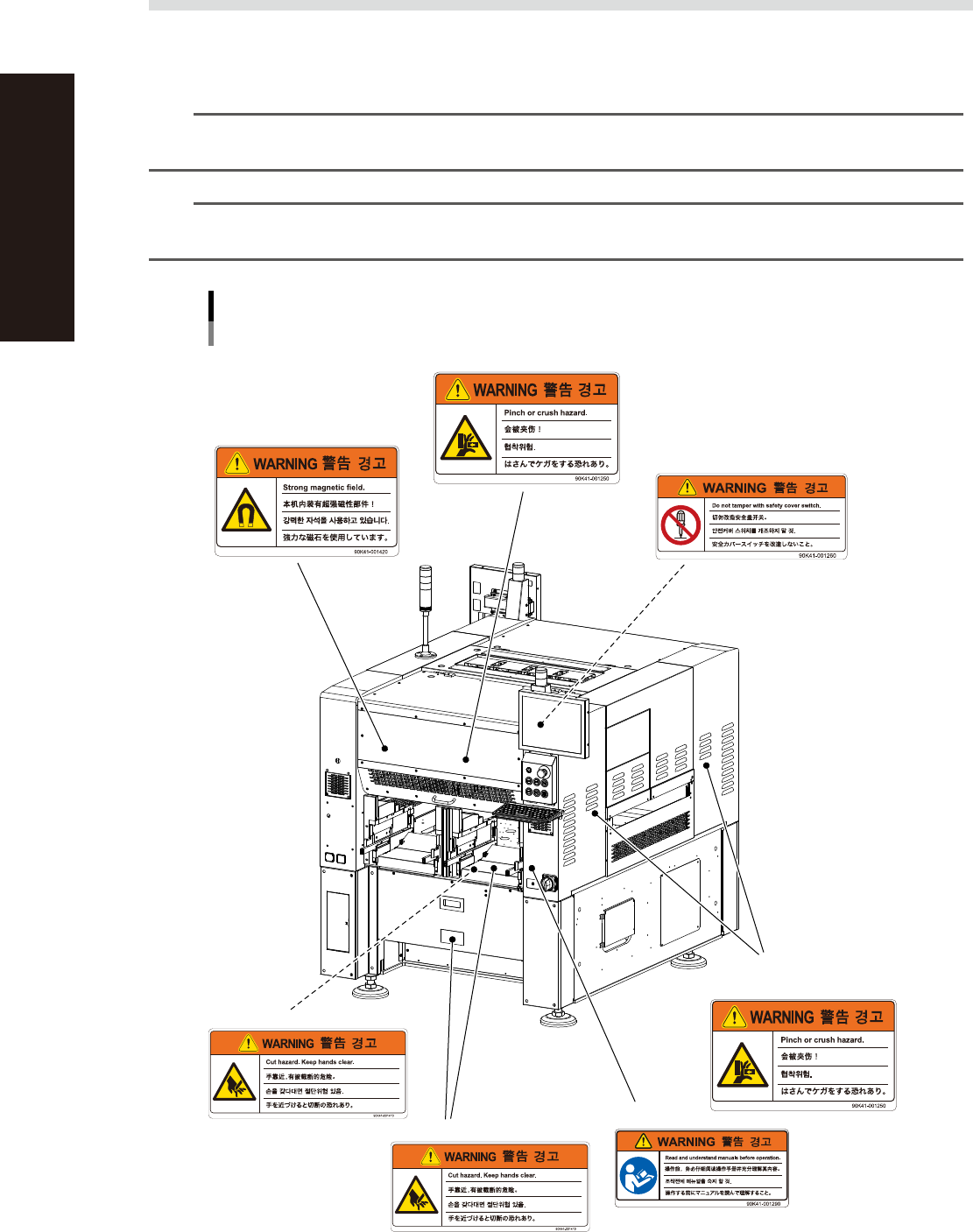
Warning/caution labels
Front 1
n Open/close cover inner side
(front and rear sides)
n Conveyor opening
(front and rear sides, right and
left sides)
n Cutter section
n Open/close cover (front and rear sides)
n Open/close cover
(front and rear sides)
n Main switch
n Cutter inner side
93201-L2-10
xxix
Safety instructions
n
Label positions
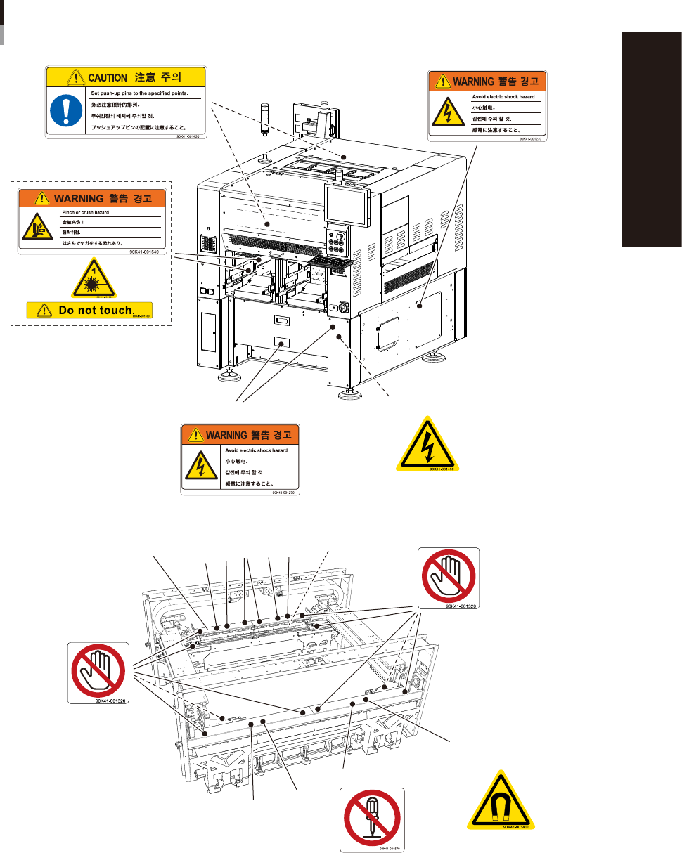
Warning/caution labels
Front 2
■ Feeder setup section
(2 locations each on front and rear sides)
■ X axis frame section inner side (front and rear sides)
■ Y axis linear scale
■ Lower panels
(front and rear sides)
3
3
2. Disassembly prohibited.
2
2
3
2
1
1. Never touch.
1. Never touch.
■ Panel inner side
■ Right and left sides
3. Caution on strong
magnetic fields
Linear cover
Linear motor
93202-L2-20
xxx
Safety instructions
n
Label positions
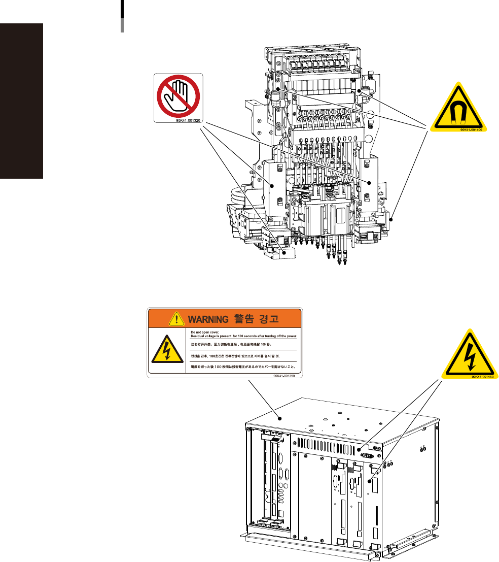
Warning/caution labels
■ Head assembly
■ Camera unit
■ SC-axis linear scale section
■ Controller
■ Top of controller
■ Controller front panel
93204-L2-20