mi14061267.pdf - 第11页
Micromachines 2023 , 14 , 1267 11 of 17 Micromachines 20 23 , 14 , x FOR PEER REVIEW 19 of 28 The nozzle diam eter is 0. 2mm The nozzle d ia m e ter is 0.25 mm The nozzle diameter is 0.3mm The nozzle d ia m e ter is 0.35…
Micromachines 2023, 14, 1267 10 of 17
Micromachines 2023, 14, x FOR PEER REVIEW 17 of 28
200CS
125CS
150CS
175CS
10CS
100CS
50CS
Droplet volume [ L ]
0 0.00005 0.0001 0.00015 0.0002 0.00025 0.0003
Time [ s ]
0
8
410
−
×
8
310
−
×
8
210
−
×
8
110
−
×
8
110
−
−×
8
210
−
−×
Figure 16. The change in the volume of droplets ejected caused by the change in oil viscosity.
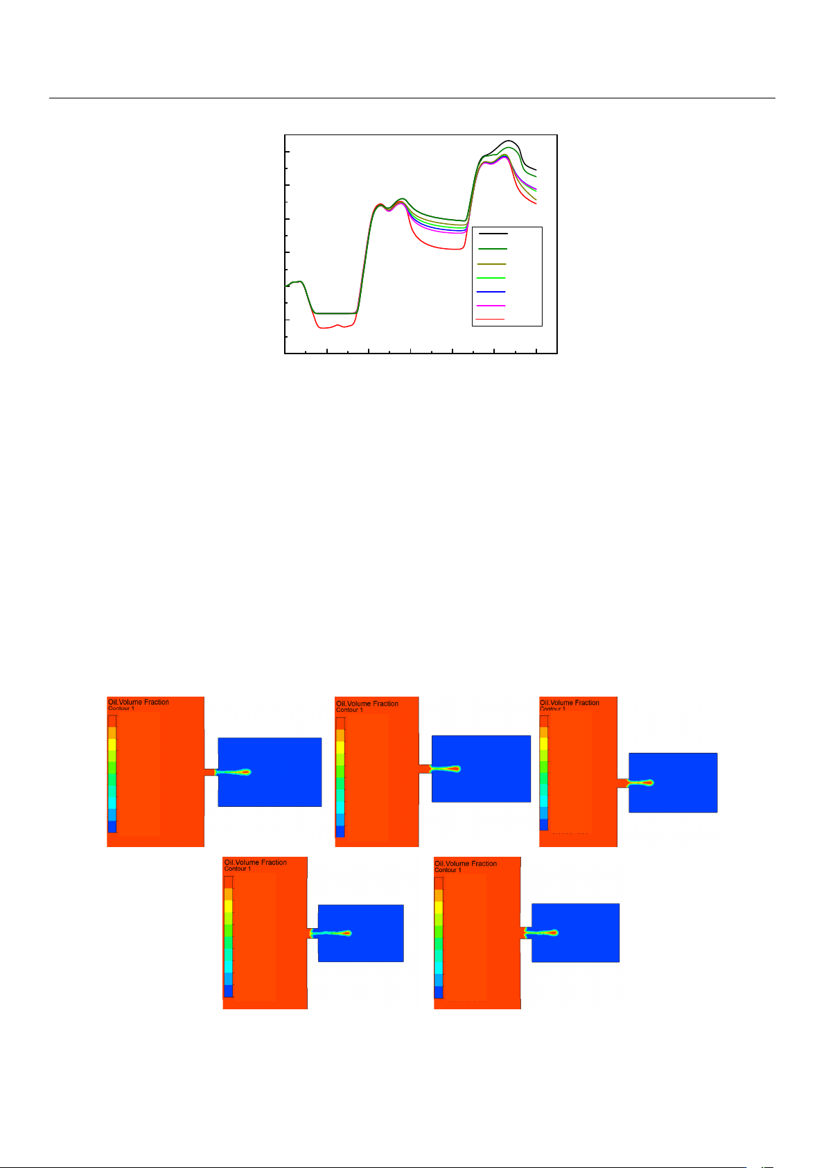
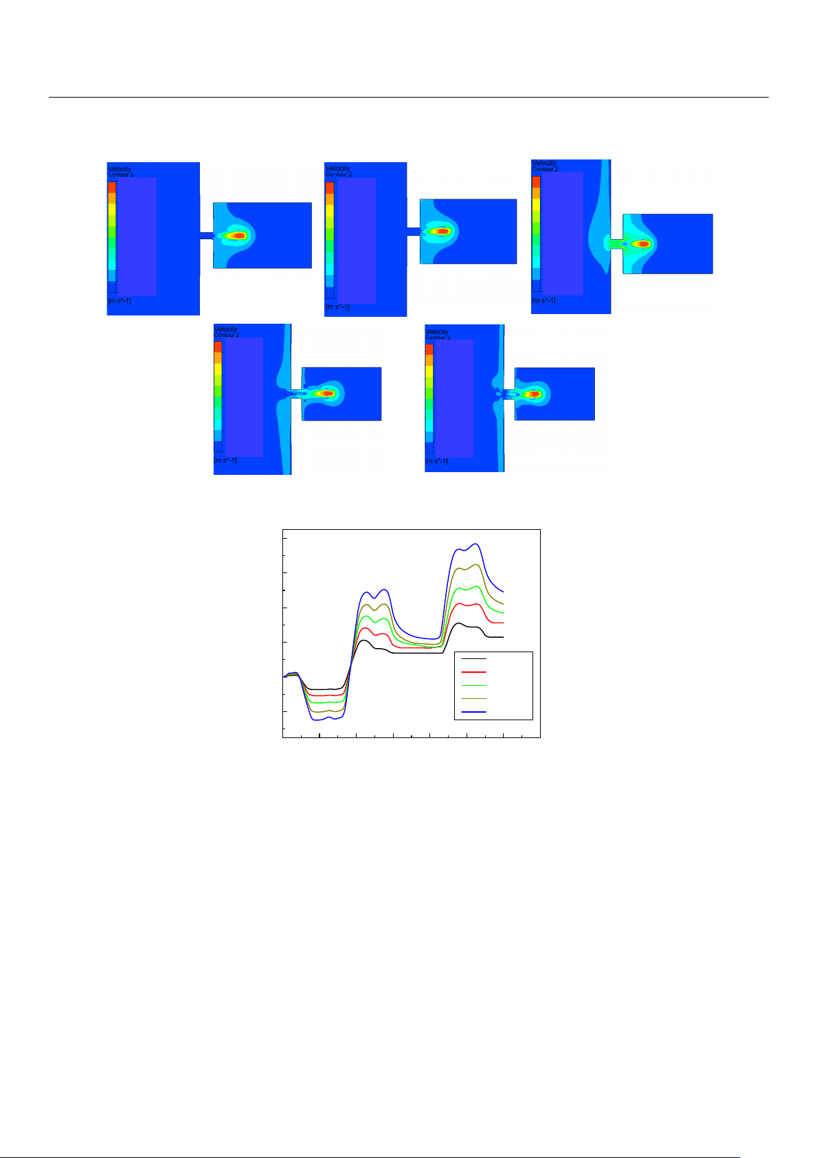
The influence of the change in nozzle diameter on the injection performance is shown
in Figures 17–19. Figure 17 shows the influence of the change in nozzle diameter on the
ejection state of the droplet. With the increase in nozzle diameter, the stability of the drop-
let slightly decreases, and the tail begins to jier. The larger the diameter of the nozzle, the
greater the difficulty of the droplet ejection and the later the droplet ejection time. Figure
18 shows the influence of the nozzle diameter change on the droplet outlet velocity. With
the increase in the nozzle diameter, the droplet outlet velocity gradually decreases. The
nozzle diameter can be appropriately reduced if the initial kinetic energy of the droplet is
to be increased. Figure 19 shows the influence of the nozzle diameter change on the vol-
ume of droplets. It can be seen that with the increase in the nozzle diameter, the volume
of droplets ejected by the piezoelectric micro-jet device gradually increases. If the size of
droplets ejected is to be increased to improve the injection efficiency, the nozzle diameter
can be increased.
Figure 16. The change in the volume of droplets ejected caused by the change in oil viscosity.
The influence of the change in nozzle diameter on the injection performance is shown
in Figures 17–19. Figure 17 shows the influence of the change in nozzle diameter on the
ejection state of the droplet. With the increase in nozzle diameter, the stability of the droplet
slightly decreases, and the tail begins to jitter. The larger the diameter of the nozzle, the
greater the difficulty of the droplet ejection and the later the droplet ejection time. Figure 18
shows the influence of the nozzle diameter change on the droplet outlet velocity. With
the increase in the nozzle diameter, the droplet outlet velocity gradually decreases. The
nozzle diameter can be appropriately reduced if the initial kinetic energy of the droplet
is to be increased. Figure 19 shows the influence of the nozzle diameter change on the
volume of droplets. It can be seen that with the increase in the nozzle diameter, the volume
of droplets ejected by the piezoelectric micro-jet device gradually increases. If the size of
droplets ejected is to be increased to improve the injection efficiency, the nozzle diameter
can be increased.
Micromachines 2023, 14, x FOR PEER REVIEW 18 of 28
The nozzle
diameter is 0.2mm
The nozzle diameter
is 0.25mm
The nozzle
diameter is 0.3mm
The nozzle diameter
is 0.35mm
The nozzle
diameter is 0.4mm
0.454T 0.467T 0.537T
0.6572T 0.682T
1
9.00 0×10
-1
0
8.00 0×10
-1
7.00 0×10
-1
6.00 0×10
-1
5.00 0×10
-1
4.00 0×10
-1
3.00 0×10
-1
2.00 0×10
-1
1.00 0×10
-1
1
9.00 0×10
-1
0
8.00 0×10
-1
7.00 0×10
-1
6.00 0×10
-1
5.00 0×10
-1
4.00 0×10
-1
3.00 0×10
-1
2.00 0×10
-1
1.00 0×10
-1
1
9.00 0×10
-1
0
8.00 0×10
-1
7.00 0×10
-1
6.00 0×10
-1
5.00 0×10
-1
4.00 0×10
-1
3.00 0×10
-1
2.00 0×10
-1
1.00 0×10
-1
1
9.00 0×10
-1
0
8.00 0×10
-1
7.00 0×10
-1
6.00 0×10
-1
5.00 0×10
-1
4.00 0×10
-1
3.00 0×10
-1
2.00 0×10
-1
1.00 0×10
-1
1
9.00 0×10
-1
0
8.00 0×10
-1
7.00 0×10
-1
6.00 0×10
-1
5.00 0×10
-1
4.00 0×10
-1
3.00 0×10
-1
2.00 0×10
-1
1.00 0×10
-1
Figure 17. The change in droplet ejection state caused by the change in nozzle diameter.
Figure 17. The change in droplet ejection state caused by the change in nozzle diameter.
Micromachines 2023, 14, 1267 11 of 17
Micromachines 2023, 14, x FOR PEER REVIEW 19 of 28
The nozzle
diameter is 0.2mm
The nozzle diameter
is 0.25mm
The nozzle
diameter is 0.3mm
The nozzle diameter
is 0.35mm
The nozzle
diameter is 0.4mm
0.454T
0.467T
0.537T
0.6572T 0.682T
1.50 3×10
1
0
1.33 6×10
1
1.16 9×10
1
1.00 2×10
1
8.35 1
6.68 1
5.01 0
3.34 0
1.67 0
1.67 0×10
1
1.33 3×10
1
0
1.18 5×10
1
1.03 7×10
1
8.88 5
7.40 4
5.923
4.442
2.962
1.48 1
1.48 1×10
1
1.052×10
1
0
9.34 8
8.180
7.011
5.843
4.67 4
3.506
2.337
1.16 9
1.16 9×10
1
7.01 5
0
6.235
5.45 6
4.67 6
3.89 7
3.118
2.33 8
1.559
7.79 4
7.794×10
-1
4.99 2
0
4.437
3.88 2
3.32 8
2.77 3
2.218
1.66 4
1.109
5.54 6
5.546×10
-1
Figure 18. The change in droplet outlet velocity caused by the change in nozzle diameter.
Figure 18. The change in droplet outlet velocity caused by the change in nozzle diameter.
Micromachines 2023, 14, x FOR PEER REVIEW 20 of 28
0 0.00005 0.0001 0.00015 0.0002 0.00025 0.0003 0.00035
0
Droplet volume [ L ]
Time [ s ]
0.2mm
0.25mm
0.3mm
0.35mm
0.4mm
8
410
−
×
8
310
−
×
8
210
−
×
8
110
−
×
8
110
−
−×
Figure 19. The change in the volume of droplets ejected caused by the change in nozzle diameter.
Based on the above simulation analysis, it can be seen that the frequency adjustment
in a small range has lile influence on the injection performance of the piezoelectric micro-
jet device. In order to reduce the difficulty of injection, improve the injection efficiency
and increase the droplet outlet velocity and volume, the following aspects can be consid-
ered: increasing the voltage amplitude of the input signal, reducing the nozzle diameter
and using low viscosity oil. If the main consideration is to improve the accuracy of droplet
control, we can try to reduce the voltage amplitude of the input signal, increase the nozzle
diameter and use high-viscosity oil. The voltage amplitude and the nozzle diameter have
significant influences on the droplet injection performance, while the oil viscosity has little
influence on the droplet volume, namely the control accuracy, when it is greater than 100
Pa.s. However, as the viscosity of the oil increases, the difficulty of droplet injection increases
and the outlet velocity decreases. Therefore, the piezoelectric micro-jet device is more suit-
able for ejecting droplets below 100 Pa.s. In the above simulation analysis, the micro-jet de-
vice can achieve the highest accuracy of 15.53 nL with a nozzle diameter of 0.2 mm. Under
the voltage amplitude of 200 V, the maximum injection volume of 82.21 nL can be reached;
that is, the device proposed in this work has both high efficiency and high precision.
4. Experiment Test
In the above section, the basic mechanism of micro-droplet injection is explained
through ANSYS two-phase, two-way fluid–structure coupling analysis, and the influence
of various parameters on the device′s injection performance is analyzed. In this section,
an experimental system will be set up to shoot micro-droplet injection videos with indus-
trial cameras to further verify the feasibility of the proposed device.
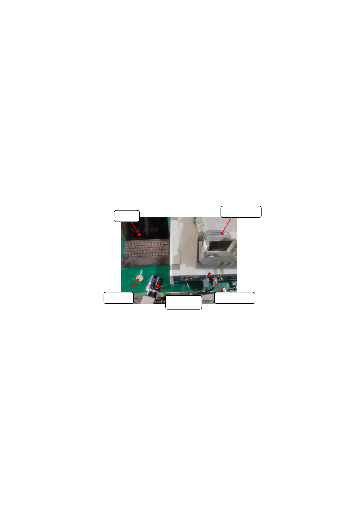
In order to verify the feasibility of the proposed device, the experimental system is
built, as shown in Figure 20. The experimental system mainly consists of a prototype, a
personal computer (PC), a signal generator (DG4162, RIGOL, Beijing, China), a power am-
plifier (ATA-4051, Aigtek Inc., Xi’an, China) and an industrial camera. The experimental
steps are as follows: firstly, the prototype is injected with a certain viscosity of viscosity
lubrication oil; then, a given square wave signal is applied in the prototype through the
signal generator and power amplifier, and then, the industrial camera is started to record
the injection process. Finally, the video taken with the industrial camera is exported and
analyzed using the PC.
Figure 19. The change in the volume of droplets ejected caused by the change in nozzle diameter.
Based on the above simulation analysis, it can be seen that the frequency adjustment in
a small range has little influence on the injection performance of the piezoelectric micro-jet
device. In order to reduce the difficulty of injection, improve the injection efficiency and
increase the droplet outlet velocity and volume, the following aspects can be considered:
increasing the voltage amplitude of the input signal, reducing the nozzle diameter and
using low viscosity oil. If the main consideration is to improve the accuracy of droplet
control, we can try to reduce the voltage amplitude of the input signal, increase the nozzle
diameter and use high-viscosity oil. The voltage amplitude and the nozzle diameter have
significant influences on the droplet injection performance, while the oil viscosity has
little influence on the droplet volume, namely the control accuracy, when it is greater than
100 Pa.s. However, as the viscosity of the oil increases, the difficulty of droplet injection
increases and the outlet velocity decreases. Therefore, the piezoelectric micro-jet device is
more suitable for ejecting droplets below 100 Pa.s. In the above simulation analysis, the
micro-jet device can achieve the highest accuracy of 15.53 nL with a nozzle diameter of
0.2 mm. Under the voltage amplitude of 200 V, the maximum injection volume of 82.21 nL
Micromachines 2023, 14, 1267 12 of 17
can be reached; that is, the device proposed in this work has both high efficiency and high
precision.
4. Experiment Test
In the above section, the basic mechanism of micro-droplet injection is explained
through ANSYS two-phase, two-way fluid–structure coupling analysis, and the influence
of various parameters on the device
0
s injection performance is analyzed. In this section, an
experimental system will be set up to shoot micro-droplet injection videos with industrial
cameras to further verify the feasibility of the proposed device.
In order to verify the feasibility of the proposed device, the experimental system is
built, as shown in Figure 20. The experimental system mainly consists of a prototype, a
personal computer (PC), a signal generator (DG4162, RIGOL, Beijing, China), a power
amplifier (ATA-4051, Aigtek Inc., Xi’an, China) and an industrial camera. The experimental
steps are as follows: firstly, the prototype is injected with a certain viscosity of viscosity
lubrication oil; then, a given square wave signal is applied in the prototype through the
signal generator and power amplifier, and then, the industrial camera is started to record
the injection process. Finally, the video taken with the industrial camera is exported and
analyzed using the PC.
Micromachines 2023, 14, x FOR PEER REVIEW 21 of 28
PC
Prototype
Industrial
camera
Signal generator
Power amplifier
Figure 20. The experimental system.
Figure 20. The experimental system.
Corresponding to the above simulation analysis, the experimental parameters are
set as follows: voltage amplitude, 100 V; square wave signal frequency, 728 Hz; nozzle
diameter, 0.4 mm; fluid viscosity, 200 Pa.s. The results of the injection experiment are shown
in Figure 21. Figure 21a shows the state of the piezoelectric micro-jet device when it is not
working, and Figure 21b–d are the injection diagrams of the piezoelectric micro-jet device
after the given square wave signal is applied. Figure 21b–d, respectively, correspond to the
droplet just being squeezed out of the nozzle, the droplet separating from the oil and being
ejected and forming satellite droplets, which are in accordance with the simulation in the
above section, further verifying the correctness of the injection mechanism revealed. It can
be seen from the observation that after the device works, the size of the droplets ejected
is uniform and the injection state is stable, which can realize long-term continuous and
stable injection, which confirms the correctness of the piezoelectric micro-jet principle and
the feasibility of the proposed piezoelectric micro-jet device. The experimental video is
attached as Video S1.