mi14061267.pdf - 第14页
Micromachines 2023 , 14 , 1267 14 of 17 Micromachines 20 23 , 14 , x FOR PEER REVIEW 24 of 28 50 100 150 200 Dr op let vo lume (L) Vo lt a ge a m p litude (V) 7900 8000 8100 8200 8300 Dr op let vo lume (L) S igna l fr eq…
Micromachines 2023, 14, 1267 13 of 17
Micromachines 2023, 14, x FOR PEER REVIEW 22 of 28
Corresponding to the above simulation analysis, the experimental parameters are set
as follows: voltage amplitude, 100 V; square wave signal frequency, 728 Hz; nozzle diam-
eter, 0.4 mm; fluid viscosity, 200 Pa.s. The results of the injection experiment are shown in
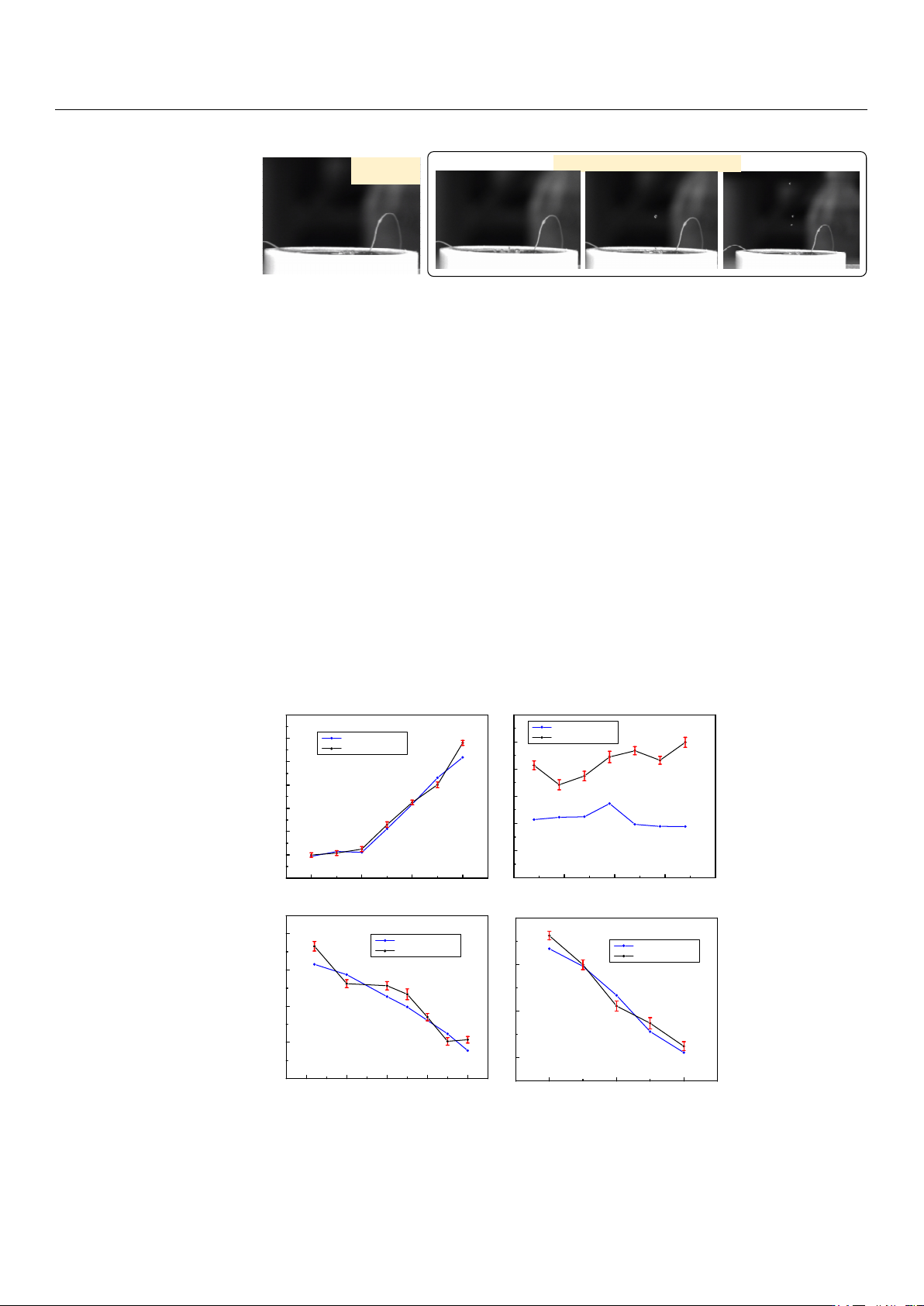
Figure 21. Figure 21a shows the state of the piezoelectric micro-jet device when it is not
working, and Figure 21b–d are the injection diagrams of the piezoelectric micro-jet device
after the given square wave signal is applied. Figure 21b–d, respectively, correspond to
the droplet just being squeezed out of the nozzle, the droplet separating from the oil and
being ejected and forming satellite droplets, which are in accordance with the simulation
in the above section, further verifying the correctness of the injection mechanism revealed.
It can be seen from the observation that after the device works, the size of the droplets
ejected is uniform and the injection state is stable, which can realize long-term continuous
and stable injection, which confirms the correctness of the piezoelectric micro-jet principle
and the feasibility of the proposed piezoelectric micro-jet device. The experimental video
is aached as Video S1.
When the device is
not working
When the device is applied a given square wave signal
a
b
cd
Figure 21. The results of the injection experiment: (a) The state of the piezoelectric micro-jet device
when it is not working; (b) the droplet just being squeezed out of the nozzle; (c) the droplet sepa-
rating from the oil and being ejected; (d) the formation of satellite droplets.
In this work, the verification experiment is carried out according to the simulation
content in the previous part. The main research is to investigate the outlet velocity and
droplet volume of the piezoelectric micro-jet device under different voltage amplitudes,
signal frequencies, oil viscosities and nozzle diameters. The standard experimental condi-
tions are set as follows: voltage amplitude, 100 V; signal frequency, 8090 Hz; nozzle diam-
eter, 0.4 mm; oil viscosity, 200 Pa.s. The experimental results of the effects of voltage am-
plitude, signal frequency, oil viscosity and nozzle diameter on droplet outlet velocity
when other experimental conditions remain unchanged are shown in Figure 22. The ex-
perimental results are consistent with the simulation results in the above part, and the
errors are all within the acceptable range. The maximum error of Figure 22a–d is 11.93%,
11.53%, 8.797% and 11.55%, respectively. The experimental results of the effects of voltage
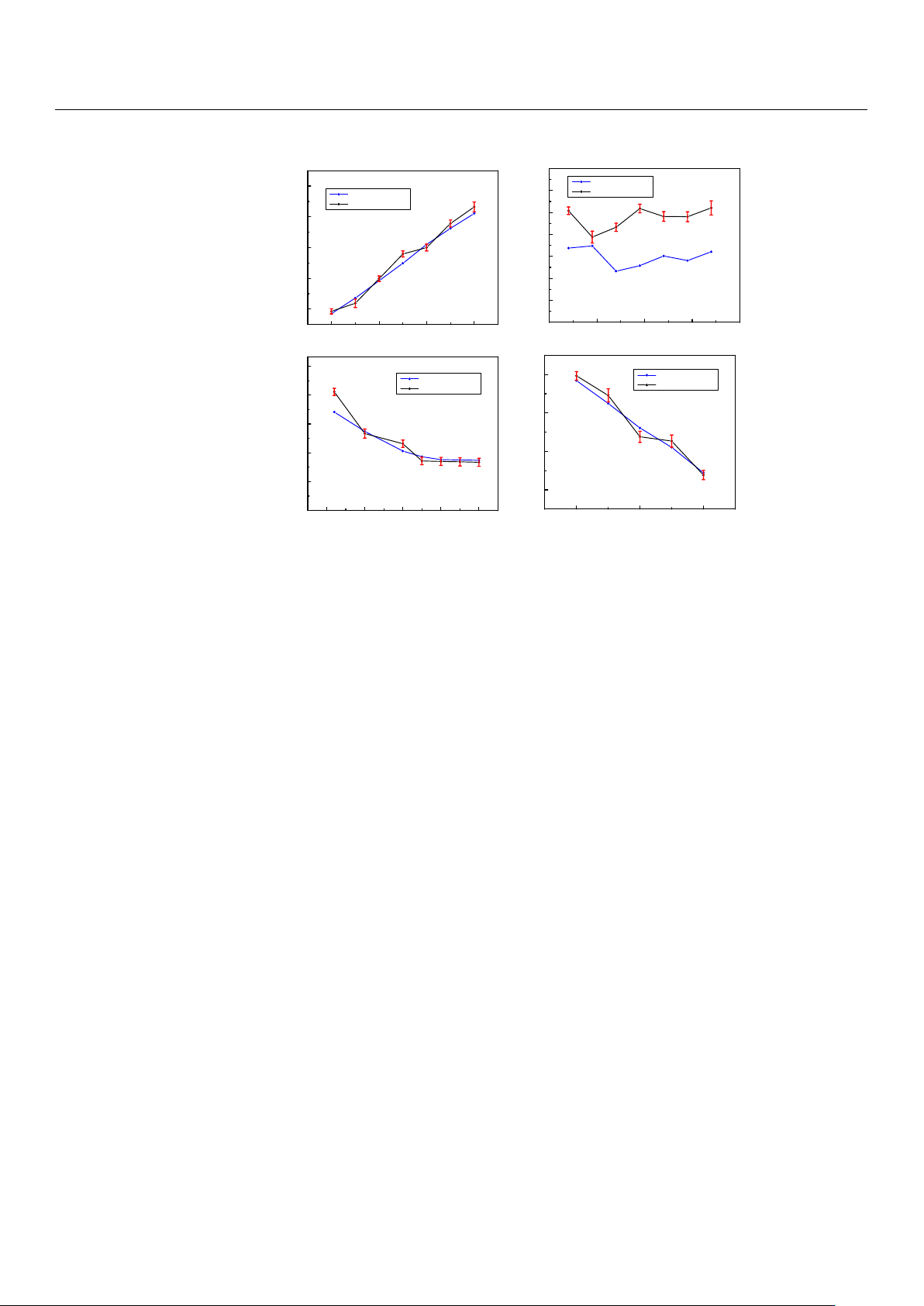
amplitude, signal frequency, oil viscosity and nozzle diameter on droplet volume when
other experimental conditions remain unchanged are shown in Figure 23. The experi-
mental results are consistent with the simulation results in the above section, and the er-
rors are all within the acceptable range. The maximum error in Figure 23a–d is 12.17%,
6.92%, 4.86% and 9.61%, respectively.
Figure 21.
The results of the injection experiment: (
a
) The state of the piezoelectric micro-jet device
when it is not working; (
b
) the droplet just being squeezed out of the nozzle; (
c
) the droplet separating
from the oil and being ejected; (d) the formation of satellite droplets.
In this work, the verification experiment is carried out according to the simulation
content in the previous part. The main research is to investigate the outlet velocity and
droplet volume of the piezoelectric micro-jet device under different voltage amplitudes,
signal frequencies, oil viscosities and nozzle diameters. The standard experimental con-
ditions are set as follows: voltage amplitude, 100 V; signal frequency, 8090 Hz; nozzle
diameter, 0.4 mm; oil viscosity, 200 Pa.s. The experimental results of the effects of voltage
amplitude, signal frequency, oil viscosity and nozzle diameter on droplet outlet velocity
when other experimental conditions remain unchanged are shown in Figure 22. The ex-
perimental results are consistent with the simulation results in the above part, and the
errors are all within the acceptable range. The maximum error of Figure 22a–d is 11.93%,
11.53%, 8.797% and 11.55%, respectively. The experimental results of the effects of voltage
amplitude, signal frequency, oil viscosity and nozzle diameter on droplet volume when
other experimental conditions remain unchanged are shown in Figure 23. The experimental
results are consistent with the simulation results in the above section, and the errors are all
within the acceptable range. The maximum error in Figure 23a–d is 12.17%, 6.92%, 4.86%
and 9.61%, respectively.
Micromachines 2023, 14, x FOR PEER REVIEW 23 of 28
50 100 150 200
0
5
10
15
20
25
30
35
Velocity (m/s)
Voltage amplitude (V)
7900 8000 8100 8200 8300
5.0
5.2
5.4
5.6
5.8
6.0
6.2
Velocity ( m/s)
Signal frequency (Hz)
0 50 100 150 200
4
6
8
10
12
Velocity (m/s)
Oil viscosity (cs)
0.2 0.3 0.4
5
10
15
20
Velocity (m/s)
Nozzle diameter (m)
Simulation result
Experimental result
a
b
c
d
Simulation result
Exp erimental result
Simulation result
Experimental result
Simulation result
Experimental result
Figure 22. The experimental results of voltage amplitude, signal frequency, oil viscosity and nozzle
diameter on droplet outlet velocity: (a) The experimental results of voltage amplitude on droplet
outlet velocity; (b) the experimental results of signal frequency on droplet outlet velocity; (c) the
experimental results of oil viscosity on droplet outlet velocity; (d) the experimental results of nozzle
diameter on droplet outlet velocity.
Figure 22.
The experimental results of voltage amplitude, signal frequency, oil viscosity and nozzle
diameter on droplet outlet velocity: (
a
) The experimental results of voltage amplitude on droplet
outlet velocity; (
b
) the experimental results of signal frequency on droplet outlet velocity; (
c
) the
experimental results of oil viscosity on droplet outlet velocity; (
d
) the experimental results of nozzle
diameter on droplet outlet velocity.
Micromachines 2023, 14, 1267 14 of 17
Micromachines 2023, 14, x FOR PEER REVIEW 24 of 28
50 100 150 200
Droplet volume (L)
Voltage amplitude (V)
7900 8000 8100 8200 8300
Droplet volume (L)
Signal frequency (Hz)
0 50 100 150 200
Droplet volume (L)
Oil viscosity (cs)
0.2 0.3 0.4
Droplet volume (L)
Nozzle diameter (m)
a
b
c
d
Simulation result
Exp erimenta l result
Simulation result
Exp erimenta l result
Simulation result
Exp erime ntal result
Simulation result
Experimental result
7
110
−
×
8
810
−
×
8
610
−
×
8
410
−
×
8
210
−
×
8
4.2 10
−
×
8
4.1 10
−
×
8
4.0 10
−
×
8
3.9 10
−
×
8
3.8 10
−
×
8
3.7 10
−
×
8
3.6 10
−
×
8
3.5 10
−
×
8
4.8 10
−
×
8
4.5 10
−
×
8
4.2 10
−
×
8
3.9 10
−
×
8
3.6 10
−
×
8
3.3 10
−
×
8
410
−
×
8
210
−
×
8
310
−
×
8
110
−
×
Figure 23. The experimental results of voltage amplitude, signal frequency, oil viscosity and nozzle
diameter on droplet volume: (a) The experimental results of voltage amplitude on droplet volume;
(b) the experimental results of signal frequency on droplet volume; (c) the experimental results of
oil viscosity on droplet volume; (d) the experimental results of nozzle diameter on droplet volume.
Figure 23.
The experimental results of voltage amplitude, signal frequency, oil viscosity and nozzle
diameter on droplet volume: (
a
) The experimental results of voltage amplitude on droplet volume;
(
b
) the experimental results of signal frequency on droplet volume; (
c
) the experimental results of oil
viscosity on droplet volume; (d) the experimental results of nozzle diameter on droplet volume.
The nozzle-driven piezoelectric micro-jet device proposed in this work is not like the
traditional piezoelectric micro-jet device; due to the entry of bubbles, the stability of the
device will gradually decline as the work progresses. Once the bubbles are entrapped,
the air bubble grows via rectified diffusion and results in a malfunction [
13
]. In addition
to excellent stability, the piezoelectric micro-jet device proposed in this paper also has
good accuracy and ejection speed. The device has a maximum drop outlet velocity of
29.056 m/s at a voltage amplitude of 200 V and a maximum drop accuracy of 13.864 nL at
a nozzle diameter of 0.2 mm. A piezoelectric micro-jet device with a pin joint designed by
Deng et al. is a typical traditional piezoelectric micro-jet device. Under the condition of an
operating frequency of 100 HZ and voltage amplitude of 100 V, 1 Pa.s adhesive is sprayed,
and its maximum control accuracy can reach about 35 nL [
24
]. The piezoelectric micro-jet
device proposed by Li et al. can obtain the injection speed of 4.7 m/s under the voltage
amplitude of 130 V, and the control accuracy can reach 4.7 nL under the signal of a 50%
duty cycle [
25
]. In summary, compared with the traditional piezoelectric micro-jet device,
the nozzle-driven piezoelectric micro-jet device proposed in this work performs well in
terms of control accuracy and ejection speed, while in terms of stability, the nozzle-driven
piezoelectric micro-jet device is better because it is not affected by bubbles.
In order to prove the stability of the proposed nozzle-driven piezoelectric micro-jet
device, a traditional piezoelectric micro-jet device is fabricated in this work, and its internal
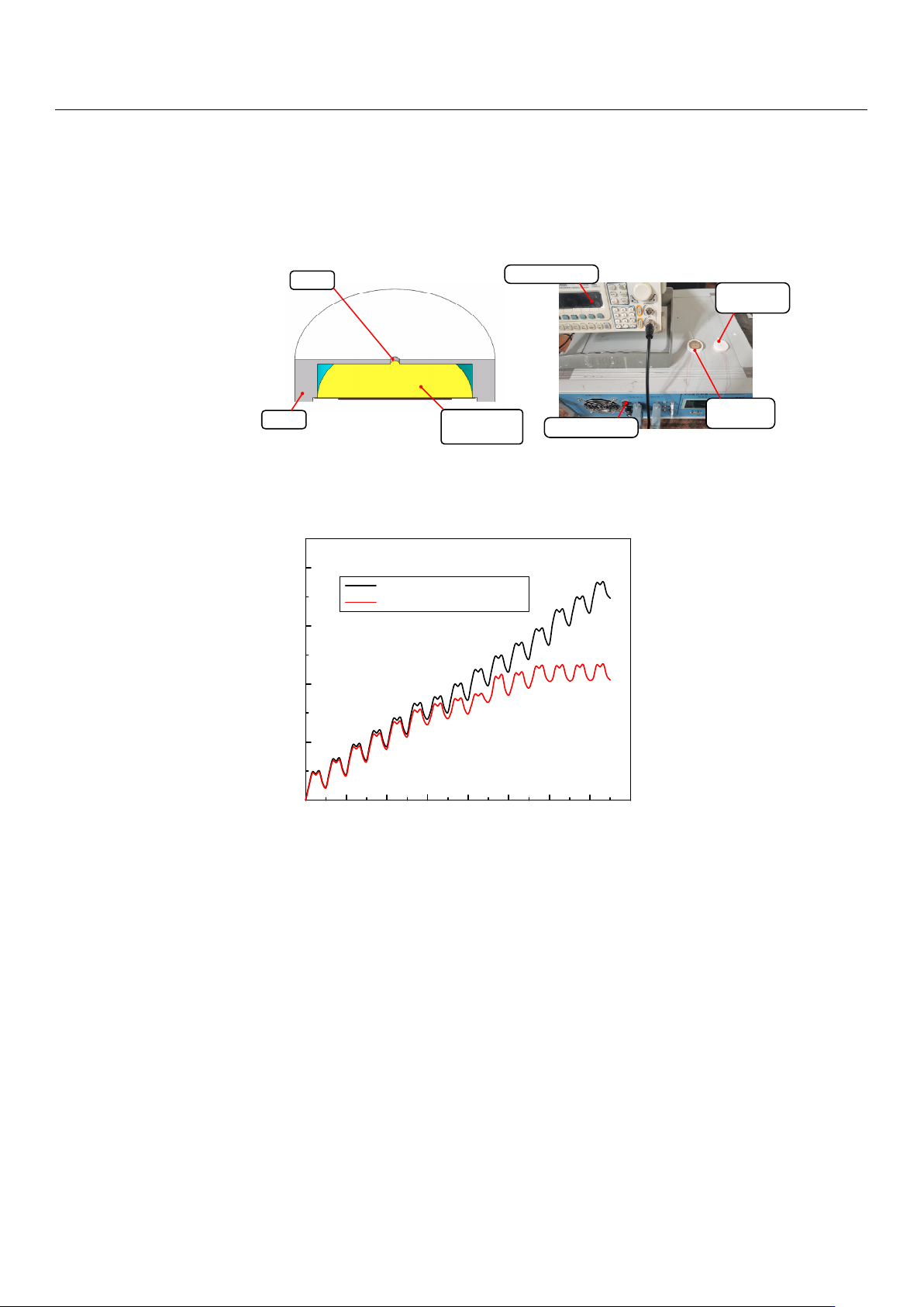
structure is shown in Figure 24a. The cavity structure and experimental settings of the
two sets of experimental devices are the same, and the experimental system built is shown
in Figure 24b. The comparison experiment steps are as follows: under the settings of a
voltage amplitude of 100 V, signal frequency of 8090 Hz, nozzle diameter of 0.4 mm and oil
viscosity of 200 cs, the same continuous pulse signal is applied to the two sets of devices
through a signal generator and power amplifier, and the volume of droplets ejected by
the devices under multiple pulses is measured. The experimental results are shown in
Figure 25. The analysis shows that both sets of devices have good ejection conditions in
the initial few cycles, and both have high control accuracy. However, with the increase in
the total working time, the ejection performance of the traditional piezoelectric micro-jet
Micromachines 2023, 14, 1267 15 of 17
device gradually decreases due to the entry of bubbles until the device almost fails. Based
on the above and experimental results, it can be seen that the nozzle-driven piezoelectric
micro-jet device proposed in this work has good stability and control accuracy compared
with the traditional piezoelectric micro-jet device.
Micromachines 2023, 14, x FOR PEER REVIEW 25 of 28
The nozzle-driven piezoelectric micro-jet device proposed in this work is not like the
traditional piezoelectric micro-jet device; due to the entry of bubbles, the stability of the
device will gradually decline as the work progresses. Once the bubbles are entrapped, the
air bubble grows via rectified diffusion and results in a malfunction [13]. In addition to
excellent stability, the piezoelectric micro-jet device proposed in this paper also has good
accuracy and ejection speed. The device has a maximum drop outlet velocity of 29.056 m/s
at a voltage amplitude of 200 V and a maximum drop accuracy of 13.864 nL at a nozzle
diameter of 0.2 mm. A piezoelectric micro-jet device with a pin joint designed by Deng et
al. is a typical traditional piezoelectric micro-jet device. Under the condition of an operat-
ing frequency of 100 HZ and voltage amplitude of 100 V, 1 Pa.s adhesive is sprayed, and
its maximum control accuracy can reach about 35 nL [24]. The piezoelectric micro-jet de-
vice proposed by Li et al. can obtain the injection speed of 4.7 m/s under the voltage am-
plitude of 130 V, and the control accuracy can reach 4.7 nL under the signal of a 50% duty
cycle [25]. In summary, compared with the traditional piezoelectric micro-jet device, the
nozzle-driven piezoelectric micro-jet device proposed in this work performs well in terms
of control accuracy and ejection speed, while in terms of stability, the nozzle-driven pie-
zoelectric micro-jet device is beer because it is not affected by bubbles.
In order to prove the stability of the proposed nozzle-driven piezoelectric micro-jet
device, a traditional piezoelectric micro-jet device is fabricated in this work, and its inter-
nal structure is shown in Figure 24a. The cavity structure and experimental seings of the
two sets of experimental devices are the same, and the experimental system built is shown
in Figure 24b. The comparison experiment steps are as follows: under the seings of a
voltage amplitude of 100 V, signal frequency of 8090 Hz, nozzle diameter of 0.4 mm and
oil viscosity of 200 cs, the same continuous pulse signal is applied to the two sets of devices
through a signal generator and power amplifier, and the volume of droplets ejected by
the devices under multiple pulses is measured. The experimental results are shown in
Figure 25. The analysis shows that both sets of devices have good ejection conditions in
the initial few cycles, and both have high control accuracy. However, with the increase in
the total working time, the ejection performance of the traditional piezoelectric micro-jet
device gradually decreases due to the entry of bubbles until the device almost fails. Based
on the above and experimental results, it can be seen that the nozzle-driven piezoelectric
micro-jet device proposed in this work has good stability and control accuracy compared
with the traditional piezoelectric micro-jet device.
Cavity
Piezoelectric
vibrator
Nozzle
Signal generator
Power amplifier
Traditional
device
Proposed
device
ab
Figure 24. The internal structure of the traditional piezoelectric micro-jet device and the comparison
experimental system: (a) The internal structure of the traditional piezoelectric micro-jet device; (b)
the comparison experimental system.
Figure 24.
The internal structure of the traditional piezoelectric micro-jet device and the comparison
experimental system: (
a
) The internal structure of the traditional piezoelectric micro-jet device; (
b
) the
comparison experimental system.
Micromachines 2023, 14, x FOR PEER REVIEW 26 of 28
0T 2T 4T 6T 8T 10T 12T 14T 16T
0
50
100
150
200
Droplet volume (nL)
Time
The proposed device
The traditional device
Figure 25. The experimental results of the comparison experiment.
5. Conclusions
In this work, a piezoelectric micro-jet device is proposed. Its unique nozzle driving
mode makes the device have many outstanding advantages that traditional piezoelectric
micro-jet devices do not have: (1) The external nozzle is different from the traditional cav-
ity vibration type, which avoids the problem that the bubble enters the cavity and reduces
the injection performance. (2) The external nozzle makes the structure of the device more
compact, and the cavity cannot consider the assembly of the vibrator and the problem of
an outlet wire. (3) The external nozzle has strong interchangeability, which can be re-
placed and repaired from time to time without remanufacturing and assembling the de-
vice.
Based on the brief description of the structure of the device and the process of micro-
jet, ANSYS two-phase, two-way fluid–structure coupling analysis is carried out, and the
mechanism of the piezoelectric micro-jet is elaborated upon in detail. On the basis of de-
termining the optimal working frequency, the influence of voltage amplitude, input signal
frequency, nozzle diameter and oil viscosity on the injection performance of the proposed
device is studied, and a set of control methods is proposed based on this. A small range
of frequency adjustment has lile influence on the injection performance. Increasing the
voltage amplitude, decreasing the nozzle diameter and decreasing the oil viscosity will
reduce the difficulty of injection, increase the droplet outlet velocity and droplet volume
and improve the injection efficiency of the device, but the control accuracy of the droplet
will decrease. In addition, when the oil viscosity is greater than 100 Pa.s, it has lile influ-
ence on the volume of droplets, namely, the control accuracy, while the influence on the
difficulty of injection and the outlet velocity of droplets still exists. This work proved the
correctness of the piezoelectric micro-jet mechanism and the feasibility of the proposed
nozzle-driven piezoelectric micro-jet device through experiments and carried out the in-
jection performance test experiment, which mainly investigated the effects of voltage am-
plitude, signal frequency, oil viscosity and nozzle diameter on the droplet outlet velocity
and droplet volume. The experimental results showed that the piezoelectric micro-jet de-
vice has a maximum droplet outlet velocity of 29.056 m/s and a maximum droplet volume
of 86.45 nL at a voltage amplitude of 200 V, while the device can achieve a maximum
droplet accuracy of 13.864 nL at a nozzle diameter of 0.2 mm. From the above mentioned,
it can be seen that the device combines high precision and high efficiency excellently. The
experimental results coincide with the ANSYS simulation results, which confirms the cor-
rectness of the simulation experiment. Finally, a comparation experiment is carried out in
this work, and the stability and superiority of the proposed device are verified by the ex-
periment with the traditional piezoelectric micro-jet device.
Figure 25. The experimental results of the comparison experiment.
5. Conclusions
In this work, a piezoelectric micro-jet device is proposed. Its unique nozzle driving
mode makes the device have many outstanding advantages that traditional piezoelectric
micro-jet devices do not have: (1) The external nozzle is different from the traditional cavity
vibration type, which avoids the problem that the bubble enters the cavity and reduces
the injection performance. (2) The external nozzle makes the structure of the device more
compact, and the cavity cannot consider the assembly of the vibrator and the problem of
an outlet wire. (3) The external nozzle has strong interchangeability, which can be replaced
and repaired from time to time without remanufacturing and assembling the device.
Based on the brief description of the structure of the device and the process of micro-
jet, ANSYS two-phase, two-way fluid–structure coupling analysis is carried out, and the
mechanism of the piezoelectric micro-jet is elaborated upon in detail. On the basis of
determining the optimal working frequency, the influence of voltage amplitude, input
signal frequency, nozzle diameter and oil viscosity on the injection performance of the
proposed device is studied, and a set of control methods is proposed based on this. A
small range of frequency adjustment has little influence on the injection performance.
Increasing the voltage amplitude, decreasing the nozzle diameter and decreasing the oil