YS100_Ope_E.pdf - 第45页
1-10 1 Part names and functions Nozzle station for FNC head 31X type (FNC-A) H5-315A H3-315A H1-315A H7-314A H5-313A H1-314A H3-314A H5-314A H3-313A H7-315A H7-313A H1-313A H1-302A H1-312A H3-312A H5-312A H7-312A 35 32 3…
1-9
1
Part names and functions
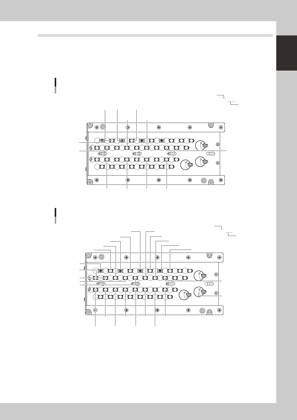
3.3 Nozzle station (option)
The nozzle station accommodates various nozzles for automatic change.
The YS100/FNC with an optional nozzle station enables automatic nozzle change on Heads 1, 3, 5 and 7 (not
on Heads 2, 4, 6 and 8). The YS100/SF with an optional nozzle station enables automatic nozzle change on all
heads.
The drawings below show the nozzle station No. and the allotted head No. and mating nozzle type.
Nozzle station for FNC head
30X type
H1-304A
H1-301A
H7-304A
H3-304A
H1-302A
H3-302AH5-302A
H7-302A
H3-301AH5-301AH7-301A
8 7 6 5 4 3 2 1
33
34
35
32 31 30 29 28 27 26 25
38 37
36
40 39
16 15 14 13 12 11 10 9
24 23 22 21 20 19 18 17
H3-304A
H1-302A
Nozzle No.
Head No.
23113-L1-00
Nozzle station for SF head
30X type
H4-302A
H5-304A
H3-304A
H6-302A
H1-304A
H8-303A
H5-302A
H2-303A
H4-303A
H2-302A
H6-303A
H3-302A
H8-302A
H7-304A
H7-302A
H1-302A
H1-302A
H1-301A
H2-301AH4-301AH6-301AH8-301A
H3-301AH5-301AH7-301A
35
32 31 30 29 28 27 26 25
38 37
40 39
24 23 22 21 20 19 18 17
8 7 6 5 4 3 2 1
33
34
36
16 15 14 13 12 11 10 9
H1-305A
Nozzle No.
Head No.
23112-L1-00
1-10
1
Part names and functions
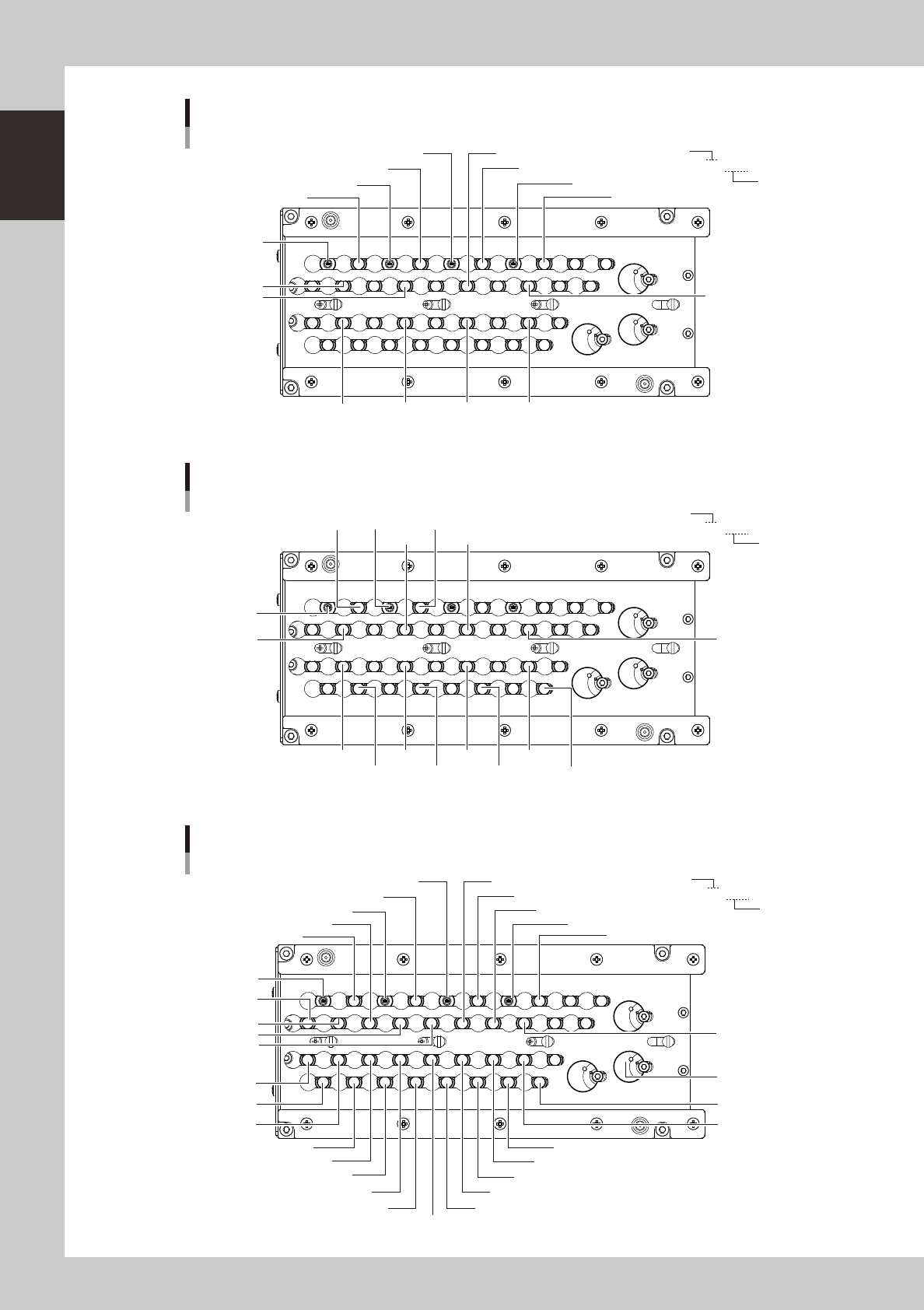
Nozzle station for FNC head
31X type (FNC-A)
H5-315A
H3-315A
H1-315A
H7-314A
H5-313A
H1-314A
H3-314A
H5-314A
H3-313A
H7-315A
H7-313A
H1-313A
H1-302A
H1-312AH3-312AH5-312AH7-312A
35
32 31 30 29 28 27 26 25
38 37
40 39
24 23 22 21 20 19 18 17
8 7 6 5 4 3 2 1
33
34
36
16 15 14 13 12 11 10 9
Nozzle No.
Head No.
23116-L1-00
Nozzle station for FNC head
31X type (FNC-B)
H1-315A
H1-312A
H1-311A
H3-311A
H5-311A
H7-311A
H7-315A
H3-315A
H1-313A
H3-313AH5-313A
H7-313A
H3-312AH5-312AH7-312A
8 7 6 5 4 3 2 1
33
34
35
32 31 30 29 28 27 26 25
38 37
36
40 39
16 15 14 13 12 11 10 9
24 23 22 21 20 19 18 17
H5-315A
H1-302A
Nozzle No.
Head No.
23124-L1-00
Nozzle station for SF head
31X type
H4-313A
H5-315A
H3-315A
H6-313A
H1-315A
H8-314A
H5-313A
H2-314A
H4-314A
H2-313A
H6-314A
H3-313A
H8-313A
H7-315A
H7-313A
H1-313A
H1-302A
H1-312A
H1-311A
H1-316A
H2-311AH7-311A
H8-311A
H2-312AH6-312A
H3-311AH6-311A
H3-312AH5-312A
H4-311A
H4-312A
H5-311A
H8-312A
H7-312A
35
32 31 30 29 28 27 26 25
38 37
40 39
24 23 22 21 20 19 18 17
8 7 6 5 4 3 2 1
33
34
36
16 15 14 13 12 11 10 9
Nozzle No.
Head No.
23127-L1-00
1-11
1
Part names and functions
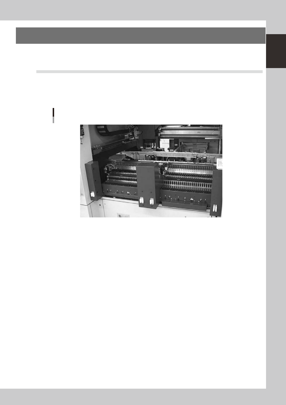
4. Component supply section
The feeder setup section is equipped with feeder plates for installing feeders such as tape feeders, and
power supply connectors and air connectors for driving optional units.
4.1 Supplying components from feeder plates
4.1.1 Fixed feeder plates
Tape feeders, bulk feeders and stick feeders are installed on the feeder plates, and operate by electric power
supplied from the mounter.
Feeder plate
23108-L1-00
Power supply connector
When using optional units such as stick feeders, plug the power cord into these connectors.
Air connector
Use these air connectors when using an optional device such as an air blow gun. Connect the air tube (outer diameter
4mm) to supply compressed air to the optional device from the mounter.