YS100_Ope_E.pdf - 第47页
1-12 1 Part names and functions n Feeder bank layout and number of max. feeders Feeder bank layout N 24-feeder bank N 32-feeder bank Feeder set No. Layout Head No. T ype Front Rear Standard type or dYTF type 1 2 3 4 5 6 …
1-11
1
Part names and functions
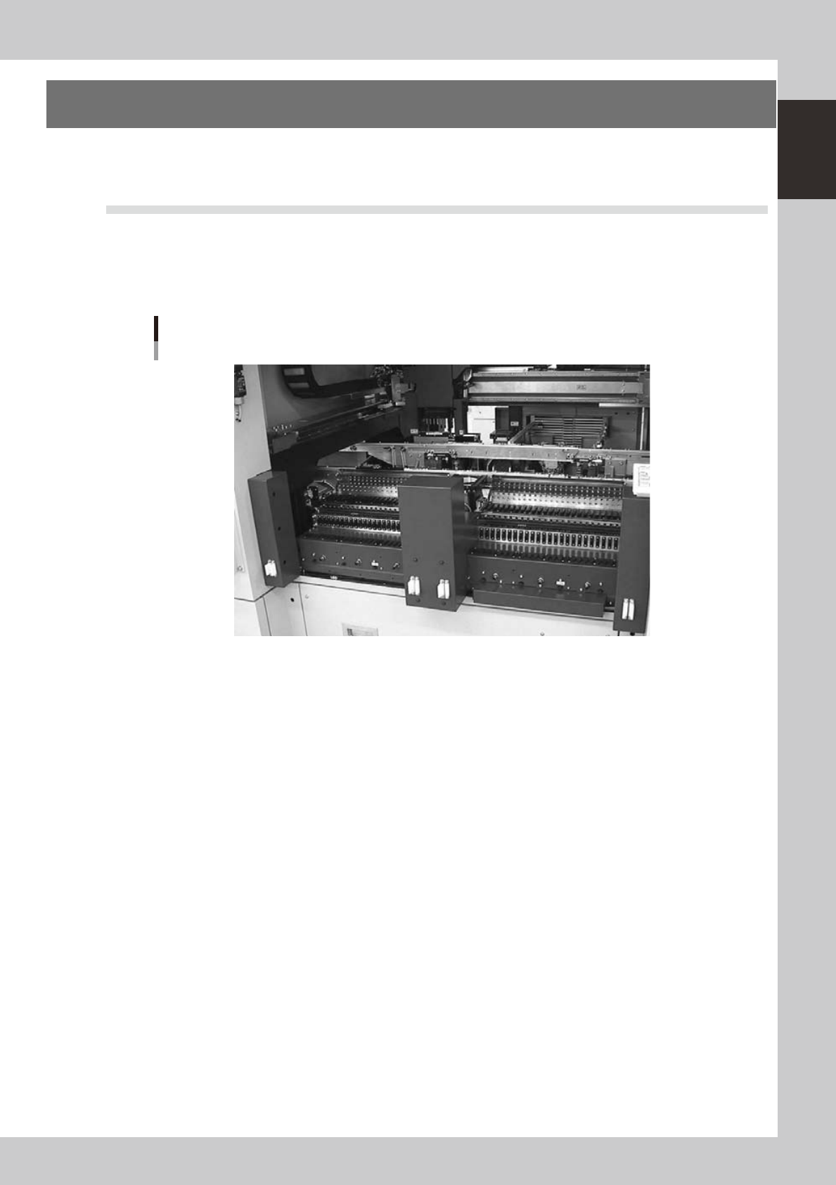
4. Component supply section
The feeder setup section is equipped with feeder plates for installing feeders such as tape feeders, and
power supply connectors and air connectors for driving optional units.
4.1 Supplying components from feeder plates
4.1.1 Fixed feeder plates
Tape feeders, bulk feeders and stick feeders are installed on the feeder plates, and operate by electric power
supplied from the mounter.
Feeder plate
23108-L1-00
Power supply connector
When using optional units such as stick feeders, plug the power cord into these connectors.
Air connector
Use these air connectors when using an optional device such as an air blow gun. Connect the air tube (outer diameter
4mm) to supply compressed air to the optional device from the mounter.
1-12
1
Part names and functions
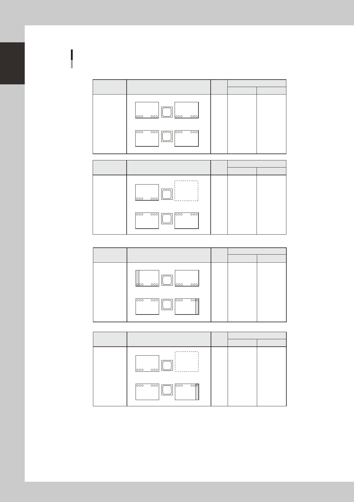
n
Feeder bank layout and number of max. feeders
Feeder bank layout
N 24-feeder bank
N 32-feeder bank
Feeder set No.
Layout
Head
No.
Type
Front Rear
Standard type
or dYTF type
1
2
3
4
5
6
7
8
1
24
25
48
148
125
124
101
RL
FL FR
RR
Layout
Head
No.
Type
Front Rear
sATS type
1
2
3
4
5
6
7
8
1 24 25 48
124 101
(12mm pitch)
RL
FL FR
s-ATS
Feeder set No.
Layout
Head
No.
Type
Front Rear
Standard type
or dYTF type
1
2
3
4
5
6
7
8
101 to 154
103 to 155
104 to 157
105 to 158
107 to 159
108 to 161
109 to 162
111 to 163
11 to 63
9 to 62
8 to 61
7 to 59
5 to 58
4 to 57
3 to 55
1 to 54
1 32 33 64
164 133 132 101
RL
FL FR
RR
Feeder set No.
Layout
Head
No.
Type
Front Rear
sATS type
1
2
3
4
5
6
7
8
101 to 114
101 to 116
101 to 117
101 to 118
101 to 120
101 to 121
101 to 122
101 to 124
11 to 63
9 to 62
8 to 61
7 to 59
5 to 58
4 to 57
3 to 55
1 to 54
1 24 32 64
124 101
(12mm pitch)
RL
FL FR
s-ATS
Feeder set No.
101 to 141
102 to 142
103 to 143
104 to 144
105 to 145
106 to 146
107 to 147
108 to 148
8 to 48
7 to 47
6 to 46
5 to 45
4 to 44
3 to 43
2 to 42
1 to 41
101 to 114
101 to 116
101 to 117
101 to 118
101 to 120
101 to 121
101 to 122
101 to 124
8 to 48
7 to 47
6 to 46
5 to 45
4 to 44
3 to 43
2 to 42
1 to 41
* Components cannot be picked up from feeder set No. 64 on the front side and No. 164 on the rear side.
* Components cannot be picked up from feeder set No. 64 on the front side.
23109-L1-10

1-13
1
Part names and functions
n
Number of max. feeders
Standard type or dYTF type sATS type
Layout
24-feeder bank
16mm pitch
32-feeder bank
12mm pitch
24-feeder bank
16mm pitch
32-feeder bank
12mm pitch
FL (Front, left side) 24 32 24 32
FR (Front, right side) 24 31 24 31
RL (Rear, left side) 24 31 24 (12mm pitch) 24
RR (Rear, right side) 24 32 --- ---
Total 96 126 72 87
n
NOTE
Rear feeder plate of sATS type is a fixed plate with 12mm pitch feeder installation holes.
n
NOTE
Accessible feeder positions may differ from the above when the Feeder Definition parameter in component
information is set to "Teach" or "Relative".