YS100_Ope_E.pdf - 第96页
2-29 2 asic operation 4. Preparing the component supply unit 4.1 T ape feeder 4.1.1 Setting the tape c Always use a tape set station or a power station to set the tape. The tape cannot be set directly on the mo…
2-28
2
asic operation
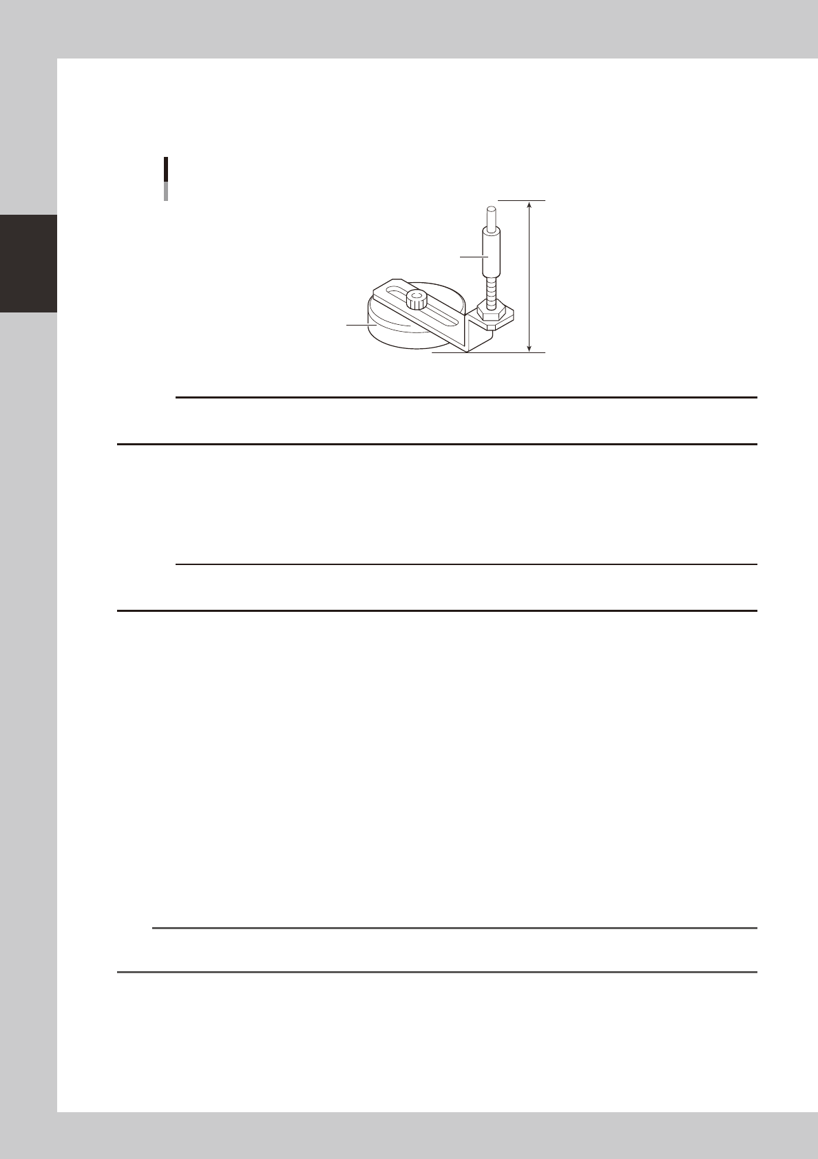
3.4.4 Push-up pins
The push-up pins are attached on the push-up plate by a magnet and used to correct downward warping of the
board.
76mm
Push-up pin
Support pin
Magnet stand
23204-L1-00
c
height.
e
1
Press the emergency stop button.
2
Place the push-up pins in the correct positions on the push-up plate.
Considering the shape and size of the board, place the push-up pins on the push-up plate so that they
uniformly support the board, including the edge of the board.
c
Set the push-up pins in positions where they will not interfere with the conveyor rails and other parts when the push-up
plate is raised.
3
Set a board on the conveyor.
Press the [Main Stopper] button on the [Unit] - [Conveyor] screen to raise the main stopper. Then set a
board on the conveyor and place it against the main stopper.
4
Cancel emergency stop.
Release the emergency stop button by turning it clockwise and press the [READY] button on the
operation panel.
5
Raise the push-up plate.
Check safety and press the [Push Up] button to raise the push-up plate. The board thickness input box
then appears. Enter the thickness of the board in millimeters and press the [OK] button. The push-up
plate moves up to secure the board.
e
6
Check that the board is uniformly clamped on the conveyor.
After pressing the emergency stop button, lightly tap on the board and also check for warping of the
board from the side. If the board is supported evenly with no warping, the adjustment is okay.
At this point, if the tips of the push-up pins do not reach the bottom of the board or the pins are pushing
the board up too much, the push-up plate height should be adjusted.
TIP
It may be convenient to mark the positions of the push-up pins on the plate (with adhesive tape, magic marker, etc.)
for each board type.
2-29
2
asic operation
4. Preparing the component supply unit
4.1 Tape feeder
4.1.1 Setting the tape
c
Always use a tape set station or a power station to set the tape. The tape cannot be set directly on the mounter.
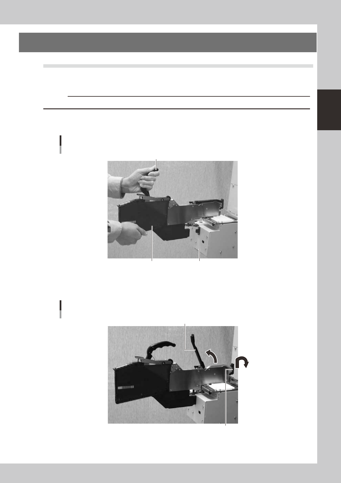
1
Set the feeder.
Place the feeder in the tape set station or power station.
Setting the feeder
Handle
Feeder Tape set station
23206-L1-00
2
Raise the tape guide assembly.
Lower the front lever for the tape guide while lifting it, and raise the tape guide assembly.
Raising the tape guide assembly
Tape guide assembly
Tape guide front lever
23207-L1-00
2-30
2
asic operation
3
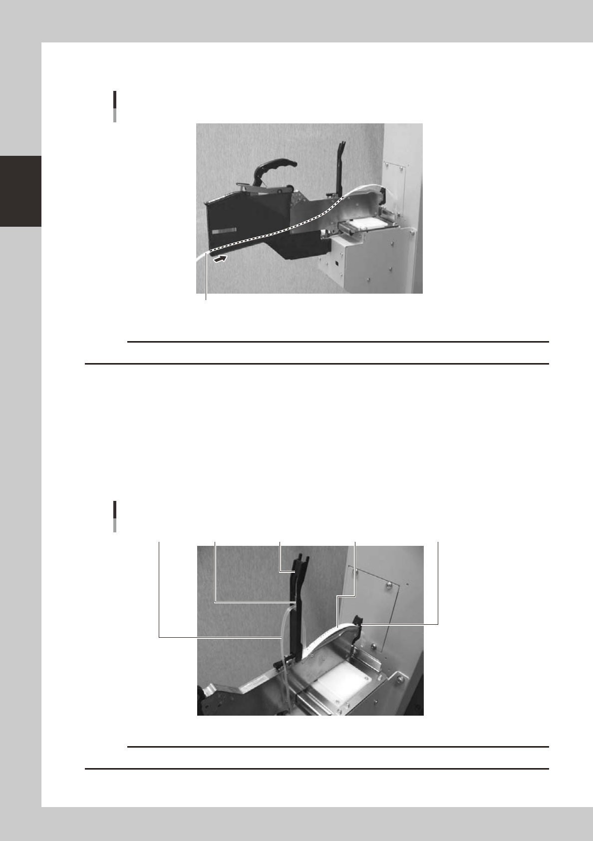
Set the tape in the tape feeder.
Insert in the hole on the rear of the feeder.
Mounting the tape
Tape
23208-L1-00
c
4
Peel off the top tape.
The tape consists of 2 layers. One is a "carrier tape" holding the electronic component and the other is a
"top tape" covering the upper surface of the component. Peel off the top tape.
5
Set the carrier tape.
Run the carrier tape through the hole in the tape guide front lever.
6
Set the top tape.
Run the top tape through the notch in the tape guide assembly. Be sure to pull out enough tape so the
top tape reaches the take-up roller.
Carrier tape and top tape
Top guide assemblyBottom plateTop tape Carrier tape Tape guide front lever
23209-L1-00
c